6 implement pump, 1 implement pump replacement, Implement pump – JLG G12-55A Service Manual User Manual
Page 130: Implement pump replacement
Hydraulic System
8-14
G10-55A, G12-55A
c. Cleaning and Drying
If contaminated hydraulic oil or foreign material is in the
tank, the tank can usually be cleaned.
Note: If a leak is suspected in the hydraulic oil reservoir,
contact your local distributor.
To clean the hydraulic oil reservoir:
1. Have a dry chemical (Class B) fire extinguisher near
the work area.
2. Remove the hydraulic oil reservoir drain plug, and
safely drain any hydraulic oil into a suitable
container. Dispose of hydraulic oil properly.
3. Clean the hydraulic oil reservoir with a high-pressure
washer, or flush the tank with hot water for five
minutes and drain the water. Dispose of
contaminated water properly.
d. Inspection
1. Inspect the hydraulic oil reservoir thoroughly for any
cracks, slices, leaks or other damage.
2. With the hydraulic oil reservoir removed from the
machine, plug all openings except one elbow fitting.
Install the elbow fitting, and apply approximately
1-1.5 psi (7-10 kPa) of air pressure through the
elbow. Check the reservoir for leaks by applying a
soap solution to the exterior and look for bubbles to
appear at the cracked or damaged area.
e. Reservoir Installation
1. Place the hydraulic oil reservoir into its original
orientation.
2. Secure the hydraulic oil reservoir to the frame with
the previous mounting hardware.
3. Uncap and connect the previously labeled hydraulic
hoses to their appropriate locations.
4. Install the hydraulic fluid level sight-glass using
special designed and drilled capscrews and gaskets.
5. Install hydraulic filter bracket and hydraulic filter.
6. Fill the hydraulic oil reservoir according to
specifications. Refer to Section 2.4, “Fluid and
Lubricant Capacities.”
7. Check the hydraulic oil reservoir for leaks.
8. Properly connect the battery.
9. Close and secure the engine cover.
10. Remove the Do Not Operate Tags from both the
ignition key switch and the steering wheel.
8.6
IMPLEMENT PUMP
For internal service instructions contact your local
distributor.
8.6.1
Implement Pump Replacement
a. Pump Removal
1. Park the machine on a firm, level surface, level the
machine, fully retract the boom, lower the boom,
place the transmission control lever in (N) NEUTRAL,
engage the park brake and shut the engine OFF.
2. Place a Do Not Operate Tag on both the ignition key
switch and the steering wheel, stating that the
machine should not be operated.
3. Open the engine cover. Allow the system fluids to
cool.
4. Properly disconnect the battery.
5. Drain the hydraulic reservoir. Refer to Section 8.5.1,
“Hydraulic Oil Reservoir Draining.”
6. Thoroughly clean the pump and surrounding area,
including all hoses and fittings before proceeding.
Note: Cap all hoses as you remove them to prevent
unnecessary fluid spillage.
7. Label, disconnect and cap the hydraulic hoses
attached to the pump.
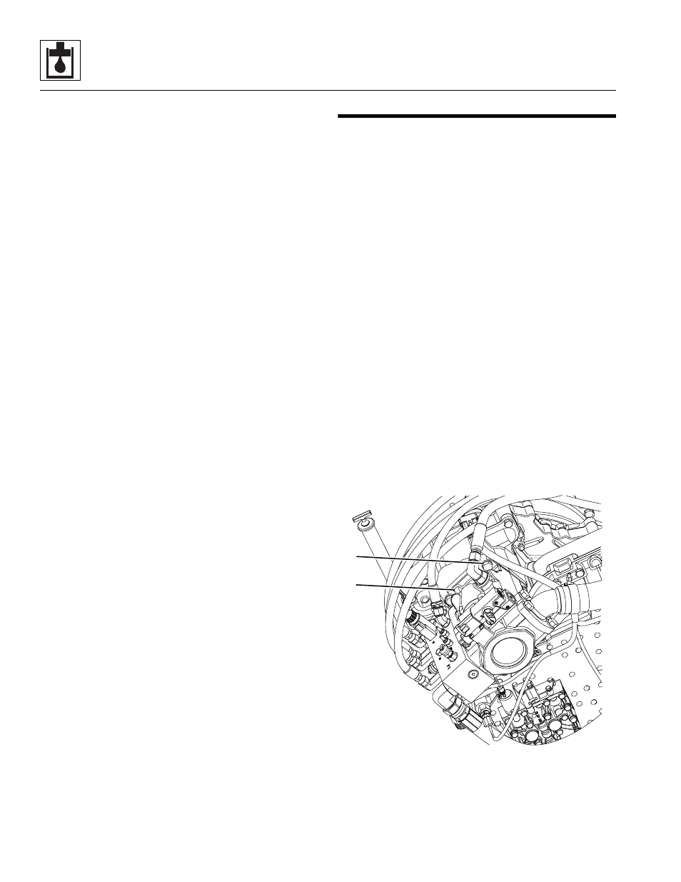
8. Remove the four bolts and lockwashers (2) securing
the pump to the transmission (top bolts shown only).
Remove the o-ring located between the transmission
and the pump. Wipe up any hydraulic oil spillage.
MAL0720
2
2