9 cab heater and fan, 1 cab heater controls, 10 solenoids, sensors and senders – JLG G12-55A Service Manual User Manual
Page 172: 1 fuel shut-off solenoid - john deere, Cab heater and fan, Solenoids, sensors and senders, Cab heater controls, Fuel shut-off solenoid - john deere
Electrical System
9-30
G10-55A, G12-55A
9.9
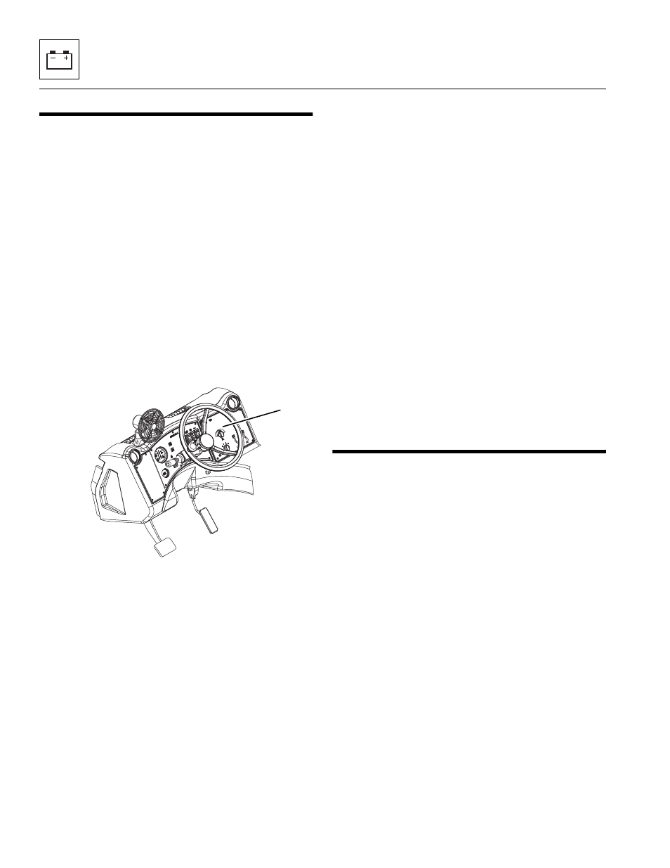
CAB HEATER AND FAN
9.9.1
Cab Heater Controls
Note: If the suspect component is found to be within the
heater box, the heater box must be removed as a
complete unit and replaced.
a. Cab Heater Controls Removal
1. Park the machine on a firm, level surface, level the
machine, fully retract the boom, lower the boom,
place the transmission control lever in
(N) NEUTRAL, engage the park brake and shut the
engine OFF.
2. Place a Do Not Operate Tag on both the ignition key
switch and the steering wheel, stating that the
machine should not be operated.
3. Open the engine cover. Allow the system fluids to
cool.
4. Properly disconnect the battery.
5. Remove the screws securing the right cab dash
panel (5).
6. Pull out the panel to gain access to the heater
control electrical connections. Disconnect the
harnesses.
7. Remove the heater control knobs.
8. Remove the necessary hardware securing the
heater control from the dash panel. Remove the
control from the panel.
b. Disassembly
DO NOT disassemble the cab heater and fan controls.
The controls are not serviceable. Replace controls if
found to be defective.
c. Installation and Testing
1. Check that the variable speed fan control is in the
OFF position.
2. Install the heater controls to the dash panel with the
previously used hardware.
3. Connect the cab electrical harness connector to the
controls.
4. Install the control knobs.
5. Install the screws securing the dash panel to the
cab.
6. Properly connect the battery.
7. Turn the ignition key to the ON position and check
the fan speeds. If further repair is needed, refer to
Section 9.5, “Electrical System Schematics.”
8. Start the machine and allow engine to warm to
operating temperature. Check heat control at
different levels.
9. Close and secure the engine cover.
10. Remove the Do Not Operate Tags from both the
ignition key switch and the steering wheel.
9.10
SOLENOIDS, SENSORS AND
SENDERS
9.10.1
Fuel Shut-off Solenoid - John Deere
a. Fuel Shut-off Solenoid Removal
1. Park the machine on a firm, level surface, level the
machine, fully retract the boom, lower the boom,
place the transmission control lever in
(N) NEUTRAL, engage the park brake and shut the
engine OFF.
2. Place a Do Not Operate Tag on both the ignition key
switch and the steering wheel, stating that the
machine should not be operated.
3. Open the engine cover. Allow the system fluids to
cool.
4. Properly disconnect the battery.
MY1230
5