JLG X700AJ Operator Manual User Manual
Page 41
SECTION 3 - MACHINE CONTROLS, INDICATORS AND OPERATION
3128790
– JLG Lift –
3-11
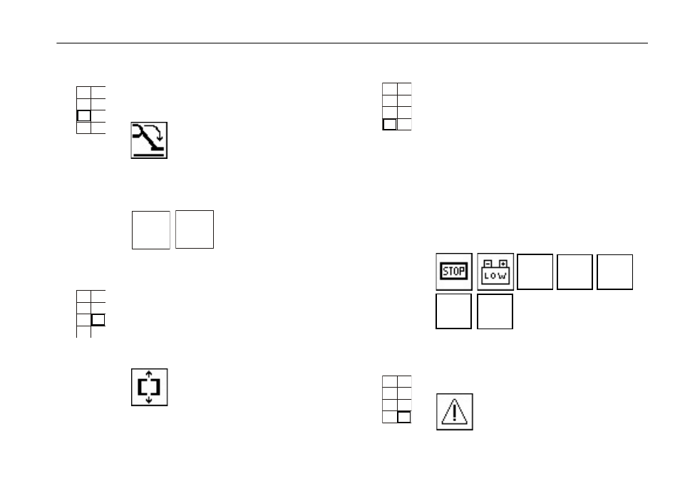
Position 5
Displays that the outriggers are properly set
and boom functions are allowed. No display
indicates that the outriggers are not properly
set and boom functions are not allowed.
If an overload occurs the main screen goes
blank for 3 seconds followed by the overload
error display and an alarm.
Position 6
Indicates that boom, jib, turntable and base
are aligned. Drive, steer, track width adjust-
ment and outrigger functions are operational
if this symbol below is present. No symbol
indicates these functions are not opera-
tional. Drive and steer are operational if all 4
outriggers are not contacting the ground.
1
2
3
4
5
6
7
8
MAX
300
LB.
MAX
440
LB.
1
2
3
4
5
6
7
8
Position 7
Can indicate any of the following situations:
• An emergency stop is pushed in (off).
• A low battery. The batteries need
charged by running the gas/diesel
engine or connecting to a power
source.
• Tower boom sensor is faulty.
• Main boom sensor is faulty. Boom func-
tions are cut out.
• Swing sensor is faulty.
• CANBUS communication is faulty.
• Electronic fault.
Position 8
Position 8 - Indicates that emergency lower-
ing has been selected.
1
2
3
4
5
6
7
8
SEN.1
FAIL
SEN.3
FAIL
SWING
?
CAN
BUS
?
CARD
?
1
2
3
4
5
6
7
8