10 front drive motor, Front drive motor – JLG 723A Service Manual User Manual
Page 95
8-13
L2906H, 2906H, 3507H, 619A, 723A, 29.6LP, 29.6, 35.7
Hydraulic System
7. Label, disconnect and cap all hydraulic hoses
attached to the pump, cap all fittings and plug hoses
to keep dirt and debris from entering the hydraulic
system.
8. Remove the two bolts that hold the pump in place.
b. Implement Pump Installation
1. Position pump in the mounting position.
Note: Use new o-rings where required. Never reuse o-
rings.
2. Apply Loctite
®
243
TM
to the mounting bolts, secure
the pump into place. Torque to 95 Nm (70 lb-ft).
3. Uncap and reconnect previously labeled hydraulic
hoses to their proper locations.
4. Fill the hydraulic reservoir with clean, filtered
hydraulic oil.
5. Prime the pump by filling the case drain port with fresh,
filtered hydraulic oil from a clean container before
installing the case drain connector and hose.
6. Check all routing of hoses and tubing for sharp
bends or interference with any rotating members. All
tube and hose clamps must be tight.
7. Properly connect the battery.
8. Start the engine and run at approximately one-third
to one-half throttle for about one minute without
moving the machine or operating any hydraulic
functions.
9. Inspect for leaks and check all fluid levels.
Note: Check for leaks and repair as required before
continuing.
10. Close and secure the engine cover.
11. Remove the Do Not Operate Tags from both the
ignition key switch and the steering wheel.
c. Pump Test
1. Perform a flow meter test on the pump.
2. Check the system functions.
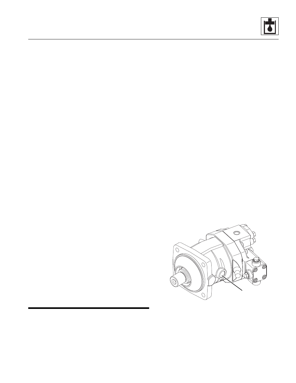
8.10
FRONT DRIVE MOTOR
For internal service instructions and detailed
specifications, contact the local JLG dealer for a copy of
the Rexroth Drive Motor Repair Manual (P/N 31200123).
a. Front Drive Motor Removal
1. Park the machine on a firm, level surface, fully
retract the boom, lower the boom, place the
transmission control lever in (N) NEUTRAL, engage
the park brake and shut the engine OFF.
2. Place a Do Not Operate Tag on both the ignition key
switch and the steering wheel, stating that the
machine should not be operated.
3. Open the engine cover. Allow the system fluids to
cool.
4. Drain the hydraulic reservoir or attach a vacuum
adapter fitting to the reservoir fill tube to reduce oil
spillage.
5. Label and disconnect all hydraulic hoses attached to
the motor, cap all fittings and plug hoses to keep dirt
and debris from entering hydraulic system.
6. Label and disconnect the electrical connection
attached to the motor,
7. Support the motor and remove the four bolts
attaching the motor to the front axle.
b. Front Drive Motor Installation
1. Install the motor onto the front axle. Torque the four
bolts to 241 Nm (178 lb-ft). Use only new seals.
2. Uncap and reconnect the previously labeled
hydraulic hoses to their appropriate locations.
3. Connect the electrical connection.
4. Fill the motor with hydraulic oil through the fill plug
(1) before starting the machine.
5. Refill the hydraulic reservoir and inspect for leaks
around the machine.
6. Close and secure the engine cover.
7. Remove the Do Not Operate Tags from both the
ignition key switch and the steering wheel.
MZ5530
1