Electrical system – JLG 723A Service Manual User Manual
Page 163
9.55
L2906H, 2906H, 3507H, 619A, 723A, 29.6LP, 29.6, 35.7
Electrical System
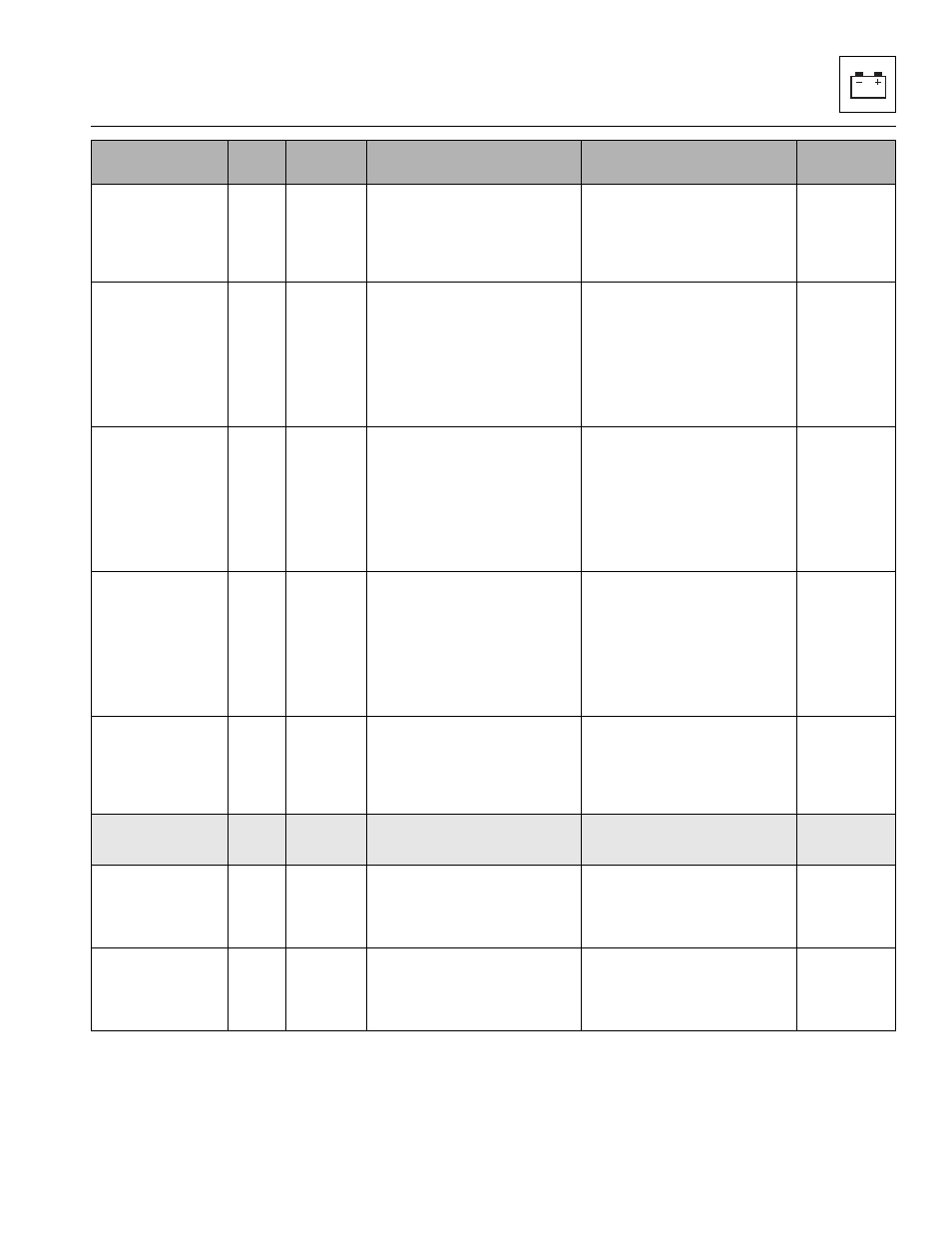
CONTINUOUS
AUXILIARY
HYDRAULICS
SWITCH HIGH AT
POWER UP
2122
1
Inhibit operation of the Continuous
Auxiliary Hydraulics feature/logic.
The UGM has detected the
Continuous Auxiliary Hydraulics
switch is HIGH at system power up.
The input
goes LOW for
a period of at
least 1
second.
JOYSTICK
TRIGGER SWITCH
ACTIVE AT POWER
UP
2123
1
Ignore command signals from the
joystick trigger switch that was
active during the power-up.
At system power-up, if the joystick
trigger switch is activated on CAT
models only.
A CAN
message is
received
indicating the
joystick
trigger switch
is not
activated.
JOYSTICK LEFT
ROLLER NOT IN
THE NEUTRAL
POSITION AT
POWER UP
2124
1
Ignore command signals from the
joystick regarding the left roller.
At system power-up, if the left roller
of the joystick is not in the neutral
position on CAT models only.
Latch fault
until a joystick
CAN message
is received
indicating the
roller is in the
neutral
position.
JOYSTICK RIGHT
ROLLER NOT IN
THE NEUTRAL
POSITION AT
POWER UP
2125
1
Ignore command signals from the
joystick regarding the right roller.
At system power-up, if the right
roller of the joystick is not in the
neutral position on CAT models
only.
Latch fault
until a joystick
CAN message
is received
indicating the
roller is in the
neutral
position.
BOOM RIDE
ENABLE SWITCH
NOT IN THE OFF
POSITION AT
POWER UP
2130
1
Ignore signal from the Boom Ride
Enable Switch.
At system power-up, the Boom
Ride/Boom Float module has
detected the Boom Ride Enable
Switch is engaged.
Boom Ride
Enable Switch
is detected in
its OFF
position.
PLATFORM
CONTROLS
22XXX
PLATFORM LEVEL –
CONFLICTING
INPUT SIGNALS
2225
1
Not acknowledge either platform
level function request messages.
If the UGM receives CAN2
messages that indicate both J1-9
and J1-10 inputs to the platform
controller are HIGH together.
Power cycled.
PLATFORM ROTATE
– CONFLICTING
INPUT SIGNALS
2226
1
Not acknowledge either platform
rotate function request messages.
If the UGM receives CAN2
messages that indicate both J1-7
and J1-8 inputs to the platform
controller are HIGH together.
Power cycled.
Message
Fault
Code
Indicators
Other Actions Taken
Trigger for Fault
Latch Until