JLG 723A Service Manual User Manual
Page 103
8-21
L2906H, 2906H, 3507H, 619A, 723A, 29.6LP, 29.6, 35.7
Hydraulic System
6. Remove the anti-kick valve from the machine. Wipe
up any hydraulic oil spillage in, on, near and around
the machine.
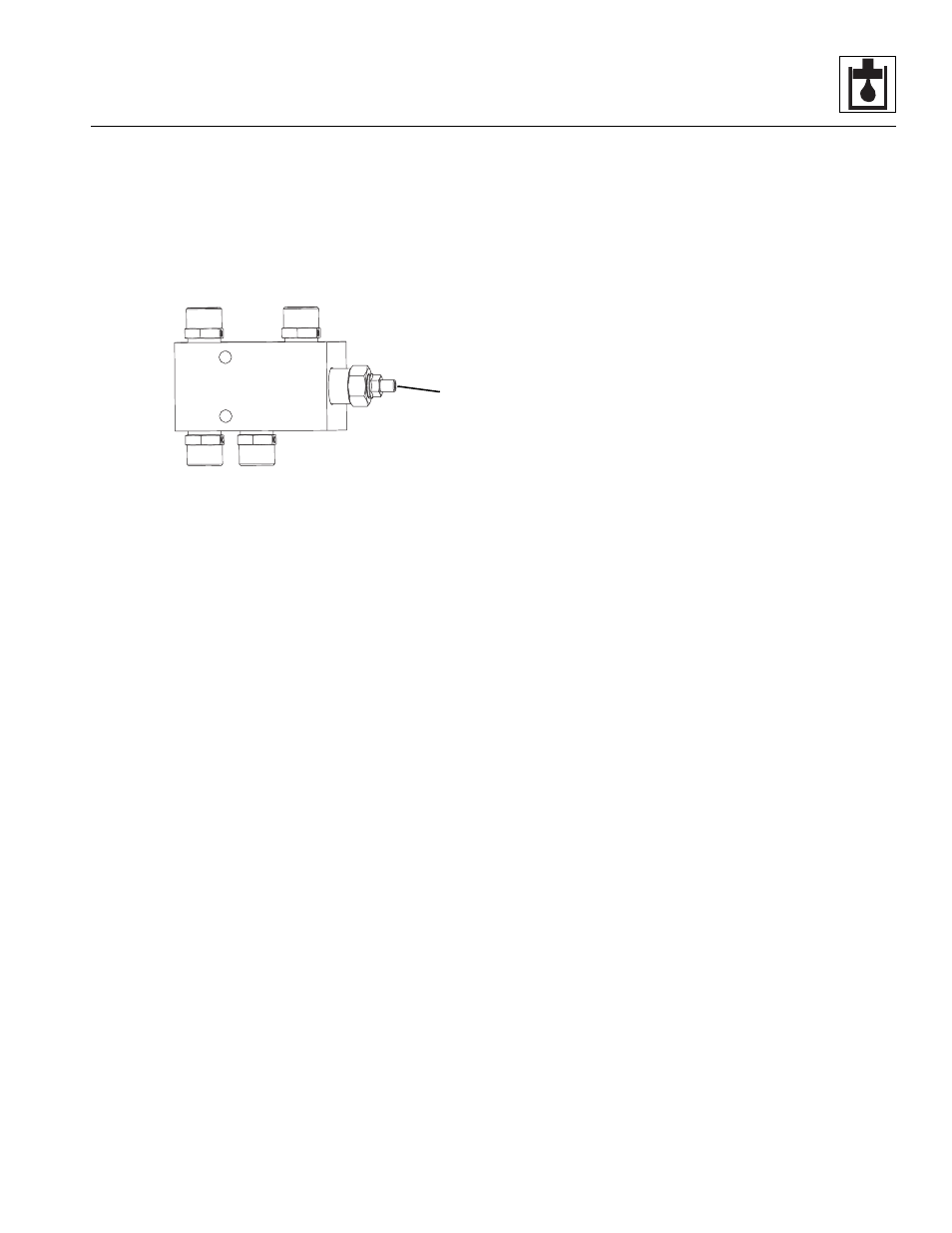
b. Anti-Kick Back Disassembly, Cleaning,
Inspection and Assembly
1. Place the anti-kick valve assembly on a suitable
work surface.
2. Label and remove the relief cartridge (3) from the
anti-kick valve housing.
3. Clean all components with a suitable cleaner before
inspection.
Note: ALWAYS replace seals, o-rings, gaskets, etc.,
with new parts to help ensure proper sealing and
operation. Lubricate seals and o-rings with clean
hydraulic oil.
4. Install the previously labeled fittings in the anti-kick
valve housing.
c. Anti-Kick Back Valve Installation
1. Attach the anti-kick valve to the mounting plate on
the frame using the socket head capscrews.
2. Connect the hydraulic hoses, fittings, etc., to the
anti-kick valve.
3. Check the routing of all hoses for sharp bends or
interference with any rotating members, and install
tie wraps and/or protective conduit as required.
Tighten all hose clamps.
4. Start the engine and run at approximately 1/3-1/2
throttle for about one minute, without moving the
machine or operating any hydraulic functions.
5. Inspect for leaks and check the level of the hydraulic
oil in the reservoir. Shut the engine OFF.
Note: Check for leaks and repair as required before
continuing. Add hydraulic oil to the reservoir as needed.
6. Wipe up any hydraulic oil spillage in, on, near and
around the machine, work area and tools.
7. Close and secure the engine cover.
8. Remove the Do Not Operate Tags from both the
ignition key switch and the steering wheel.
d. Anti-Kick Back Test
1. If further troubleshooting is required, refer to Section
MZ5560
3