IKA C 7000 Grundausstattung Set 2 User Manual
Page 42
3UHSDUDWLRQ DQG &DUU\LQJ 2XW 0HDVXUHPHQWV
IKA
-WERKE C 7000
Ver. 07 09.07
6HLWH
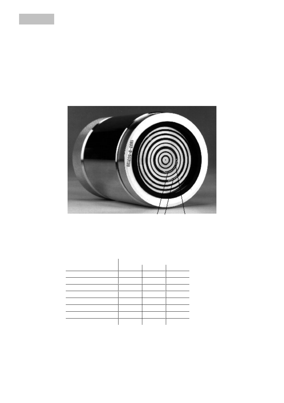
&RGLQJ
When working with the calorimeter, up to a maximum of 8 decomposition vessels
can be used. This is made possible by giving the decomposition vessels code num-
bers from 0 to 7. The calorimeter then recognises automatically which vessel is be-
ing used for a test, and selects the correct calibration parameter.
Coding is carried out by separating the narrow printed-circuit conductors on the
board mounted on the base of each decomposition vessel. The conductors are
marked I, II, and III. When separating the narrow conductors, it is vital to avoid dam-
aging the broad conductors. The conductors are separated at spacings of ca. 2 mm
using a sharp knife, and the intermediate segment removed.
1 3 2
The table below indicates which conductors must be separated for a particular code
number. For example: for code number 0, no conductors have to be separated, for
code number 3, conductors II and III must be separated.
Code number
Conductors to be separated
I
II
III
0
1
⊗
2
⊗
3
⊗
⊗
4
⊗
5
⊗
⊗
6
⊗
⊗
7
⊗
⊗
⊗
&RGLQJ
GHFRPSRVLWLRQ
YHVVHOV
1
Conductor I
2
Conductor II
3
Conductor III