Toyota l/c transfer case twin stick – Advance Adapters 7155710 User Manual
Page 3
SPECIAL NOTE:
The components packaged in this kit have been assembled and machined for specific type of conversions. Modifications to any of the components will
void any possible warranty or return privileges. If you do not fully understand modifications or changes that will be required to complete your conversion, we strongly recommend
that you contact our sales department for more information. This instruction sheet is only to be used for the assembly of Advance Adapter components. We recommend that a
service manual pertaining to your vehicle be obtained for specific torque values, wiring diagrams and other related equipment. These manuals are normally available at automotive
dealerships and parts stores.
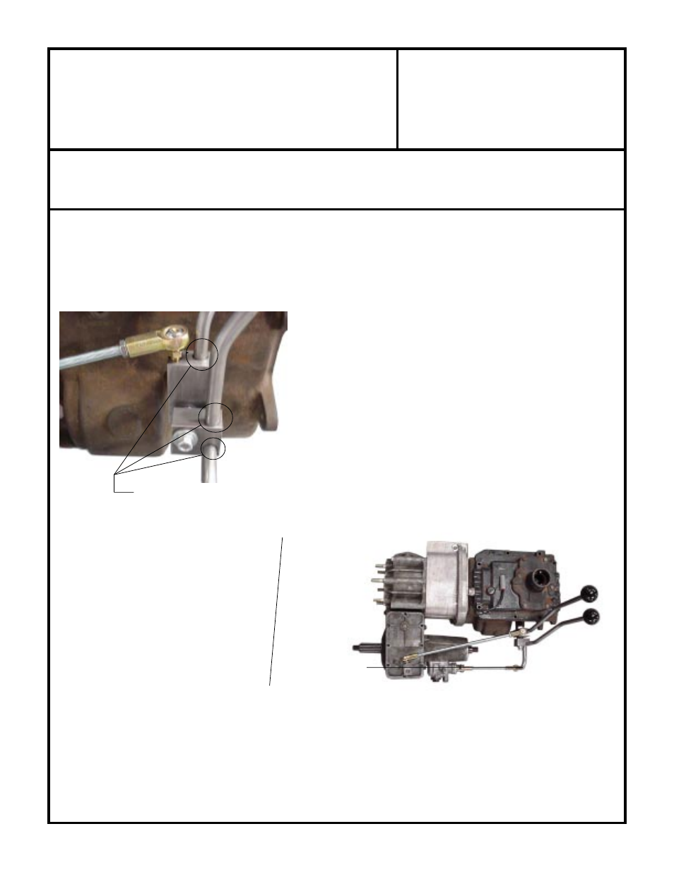
weld all the way around
Vertical alignment of
Part numbers 715588 & 715587
Horizontal alignment with Part No. 715588
ADVANCE ADAPTERS INC.
P/N: 715571
P.O. Box 247, 4320 Aerotech Center Way
New Item: (8/02)
Paso Robles, CA 93447
PAGE 3 OF 5
Telephone: (800) 350-2223
Fax: (805) 238-4201
Page Rev. Date:
09-18-02
TOYOTA L/C TRANSFER CASE TWIN STICK
INSTALLATION
Install the transfer case high/low shifter arm to the top cover of the transfer case. Since Land Cruisers had two shaft
configurations, we have provided two tapped holes on this lever. Match the tapped hole with the flat portion of the shaft.
Temporarily install the pivot shaft and both shift blocks (P/N 715575 & 715577) onto the Advance Adapters bracket. These
two blocks should be pointing straight up at the middle of their range. Paying attention to the orientation of the blocks and
where the stock hole in the floor is located, carefully bend the shift
handles (P/N 715586A) to fit your particular application. Make sure
the handles clear each other as they travel along their path. It may be
necessary at this point to enlarge the hole in the floor to gain clearance
for both handles.
Now weld each handle to its corresponding shift block, as shown.
Mode shift link P/N 715588 comes pre-bent, but the distance it sticks
out of the mode block (P/N 715577) needs to be set for your
application. Weld the mode shift link to the mode block so that it is
in-line with the mode shaft (P/N 715585) and so that the link is parallel
to the long edge of the block (straight down). See pictures “vertical
alignment” and “horizontal alignment” below for a visual description.
Note that the mode shift link may need to be cut on the non-threaded
end to achieve the desired alignment.