Mantenimiento de rutina, Loading, Especificaciones – Snorkel U Drive 25-sn1001+ User Manual
Page 8: Battery charging
8
Loading
1.
Disconnect
the
plug
from
the
battery
box
and
remove
the
battery
box
from
the
rear
of
the
machine
(Figure
7).
The
battery
box
is
heavy,
42.9
kg
(94.5
lbs.),
lift
properly
(or
have
someone
help
you)
to
prevent
back
injury.
Make
sure
loader
fully
engages
tailgate
or
vehicle
bed.
2.
Raise
the
loader
support
bracket
and
engage
the
retaining
pin
in
the
top
hole
of
the
loader
channel
(Figure
7).
3.
Secure
the
loader
to
the
loader
support
bracket
with
the
gravity
hook.
4.
Position
the
unit
so
the
back
of
the
machine
comes
in
contact
with
the
vehicle
bed
or
tail-
gate.
5.
Release
the
gravity
hook
and
slide
the
loader
down
until
it
comes
into
contact
w
ith
the
vehicle
bed
or
tailgate.
Then
reposition
the
loader
support
bracket
so
the
retaining
pin
is
in
the
first
a
vailable
hole
above
the
loader.
6.
Release
the
locking
pin
and
pull
the
handle
out
until
the
locking
pin
engages
the
hole
in
the
end
of
the
handle
(Figure
8).
7.
Lift
up
on
the
handle,
using
the
loader
as
a
pivot,
until
the
unit
rotates
to
a
horizontal
posi-
tion
in
the
vehicle
bed
(Figure
9).
8.
Push
the
base
of
the
unit
towards
the
front
of
the
vehicle
bed.
The
machine
will
slide
on
the
loader
until
the
rear
wheels
are
on
the
bed.
The
unit
may
then
be
rolled
on
the
rear
wheels
and
upper
casters.
9.
Return
the
handle
to
the
stored
position,
making
sure
the
locking
pin
engages
the
handle.
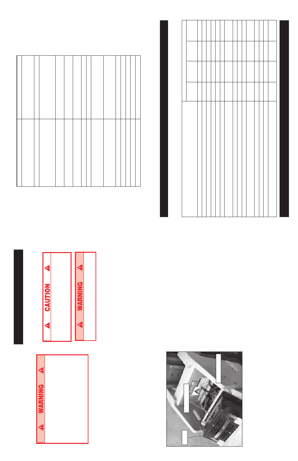
Figure 6: Battery Box
BATTERY
CHARGING
Charge
batteries
at
end
of
each
work
shift
or
sooner
if
batteries
have
been
discharged.
Charge
battery
in
a
w
ell
ventilated
area.
Do
not
charge
battery
when
the
work
platform
is
in
an
area
containing
sparks
or
flames.
Permanent
damage
to
battery
will
result
if
not
immediately
recharged
after
discharging.
Keep
charger
dry.
1.
Check
battery
fluid
level.
If
electrolyte
level
is
lower
than
10
mm
(
3
/
8
in.)
above
plates
add
distilled
water
only.
2.
Verify
charger
voltage
switch
is
set
to
12
volts.
3.
Connect
extension
cord
(1.5
mm²
(12
ga.)
conductor
m
inimum
and
15
m
(50
ft.)
in
length
maximum)
to
charger
plug.
Connect
extension
cord
to
properly
grounded
outlet
of
proper
voltage
and
frequency.
4.
Set
charger
control
to
Conventional
setting.
Charger
ammeter
should
indicate
charge
rate.
5.
When
battery
is
fully
charged,
charger
automati-
cally
turns
itself
off.
Disconnect
extension
cord.
Charger
Charger
Control
Battery
Box
Plug
37
Especificaciones*
I
TE
M
U
D
R
IV
E
2
5
Altura
plataforma
Máximo
7,62
m
(25
pies)
Mínimo
38
cm
(15
pulg.)
Capacidad
de
la
plataforma
159
kg
(350
lbs.)
Dimensiones
guardada
Alto
1,98
m
(
79
pulg.)
Ancho
84
cm
(29
pulg.)
La
rg
o
1,24
m
(
49
pulg.)
Superficie
de
apoyo
(sólo
gatos
de
rosca)
An
ch
o/
La
rg
o
1,5
m
(59
pulg.)/1,42
m
(56
pulg.)
Superficie
de
apoyo
(
con
ruedas
instaladas)
An
ch
o/
La
rg
o
2,1
m
(80,5
pulg.)/1,9
m
(
75
pulg.)
Peso
total
409,6
kg
(903
lbs.)
Caja
de
la
batería
42,9
kg
(94,5
lbs.)
Altura
de
la
baranda
1,1
m
(43,5
pulg.)
Altura
de
barra
punta
pie
152
mm
(6
pulg.)
Voltaje
sistema
Fuente
de
electricidad
CC
2
baterías
de
12
volt,
grupo
22
60
Amp/hr.,
Peso
mín.
23,6
kg
(52
lbs.)
Cargador
de
batería
120
volts,
corriente
alterna,
60
Hz
o
220
volts,
corriente
alterna,
50
Hz
Alimenta
5
amp,
24
volts,
corriente
continua
Máxima
presión
hidráulica
del
sistema
165
bar
(2400
psi)
Velocidad
de
desplazamiento
0,2
K
m/h
/ 2
MPH
Velocidad
de
elevación
22
seg.
Inclinación
máxima
1
grado
Fuerza
m
áxima
del
viento
5
escala
Beaufort
(10,1
m/sec.)
MANTENIMIENTO
DE
RUTINA
Utilice
la
siguiente
tabla
como
guía
para
mantenimiento
de
rutina.
Consulte
el
Manual
de
servicio
para
obtener
instrucciones
completas
sobre
serviio
de
mantenimiento.
OPERACIÓN
DE
MANTENIMENTO
INTERVALO
MENSUAL
C/3
MESES
ANUAL
DIARO
O
O
O
50 HR
125
HR.
500
HR.
Verifique
la
exactitud
del
nivel
de
la
burbuja
X
Revise
la
operación
de
los
mecanismos
de
enganche
del
estabilizador
X
Revise
el
nivel
del
fluido
de
la
batería
y
cargue
la
batería
(modelos
CD
solamente)
X
Verifique
que
no
existan
etiquetas
dañadas,
descoloridas
o
faltantes
y
cámbielas
X
Revise
la
condición
del
cable
de
control
X
Verifique
que
el
ensamblado
del
m
ástil
no
esté
doblado,
rajado
o
le
falten
remaches
X
Revise
la
operación
del
chasis
y
del
interruptor
de
parada
de
emergencia
de
la
plataforma
X
Revise
la
operación
de
la
válvula
de
bajada
de
emergencia
X
Verifique
que
las
ruedecillas
no
presenten
daños
X
Revise
el
nivel
de
fluido
hidráulico
X
Verifique
que
la
cabina
y
los
sujetadores
de
soporte
de
la
cabina
tengan
el
par
de
torsión
adecuado
X
Revise
y
ajuste
la
tensión
de
las
correas
de
secuencia
X
Lubrique
las
cadenas
de
elevación
y
las
roldanas
X
Cambie
el
fluido
hidráulico
(ISO
#46)
X
Compruebe
las
ruedas
tractoras
para
ver
si
hay
piezas
sueltas,
perdidas
o
desgastadas
X
*Las
especificaciones
pueden
cambiarse
sin
aviso
previo.
Cumple
o
supera
los
requisitos
de
las
directivas
CE
y
GS
sobre
maquinaria.