Battery maintenance, Operation using outriggers only – Snorkel U Drive 25-sn1001+ User Manual
Page 7
7
EMERGENCY
LOWERING
If
the
platform
should
fail
to
lower,
NEVER
climb
down
the
m
ast.
Ask
a
person
on
the
ground
to
open
the
Emer-
gency
Lowering
Valve
to
lower
the
platform.
This
valve
is
located
through
a
cutout
in
the
power
unit
cover
on
the
left
side
of
the
mast
(Figure
5).
1.
Pull
the
knob
out
and
turn
1
/
4
turn
to
open
the
Emergency
Lowering
Valve.
2.
To
close
the
Emergency
Lowering
Valve,
turn
the
knob
until
it
snaps
back
in.
Once
the
platform
is
fully
lowered,
be
certain
that
the
Emergency
Lowering
Valve
is
closed
again.
The
platform
w
ill
not
elevate
if
the
Emergency
Lowering
Valve
is
open.
AFTER
USE
EACH
DAY
1.
Ensure
that
the
platform
is
fully
lowered.
2.
Park
the
machine
on
level
ground,
preferably
under
cover.
3.
Secure
against
vandals,
children
or
unautho-
rized
operation
by
turning
the
Key
Switch
to
OFF
and
remove
the
key.
Battery
Maintenance
Hazard
of
explosive
gas
mixture.
Keep
sparks,
flame
and
smoking
materials
away
from
battery.
Always
wear
safety
glasses
when
working
with
batteries.
Battery
fluid
is
highly
corrosive.
Rinse
away
any
spilled
fluid
thoroughly
with
clean
water.
Always
replace
battery
with
UpRight
battery
or
m
anufacturer
approved
replacement
weighing
at
least
23.6
kg
(52
lbs.)
each.
Check
battery
fluid
level
daily,
especially
if
work
platform
is
being
used
in
a
warm,
dry
climate.
If
electrolyte
level
is
less
than
10
mm
(
3
/
8
in.)
above
plates
add
distilled
water
only.
DO
NOT
use
tap
water
w
ith
high
mineral
content,
it
will
shorten
battery
life.
Keep
terminals
and
tops
of
batteries
clean.
Refer
to
the
Service
Manual
to
extend
battery
life
and
for
complete
service
instructions.
Operation Using Outriggers
Only
Before
operating t
he
machine,
insure
that:
The
operator
has
been
thoroughly
trained
on
this
machine.
The
operator
has
read,
fully
understands,
and
follows
this
Operator
Manual
and
the
Scaffold
Industry
Association's
MANUAL
OF
RESPONSIBILITIES.
The
unit
has
been
properly
set
up
with
all
four
(4)
outriggers
properly
installed
and
the
base
leveled,
and
the
machine
has
passed
the
Safety
Interlock
Test.
Note:
Platform
w
ill
not
elevate
unless
all
four
outriggers
are
properly
installed
with
screwjack
pads
firmly
in
contact
w
ith
floor
and
each
outrigger
indicator
lamp
lit.
1.
Check
for
external
damage
to
the
mast.
2.
Turn
Key
to
ON
, Key
Switch
is
located
on
the
left
side
of
the
mast
(Figure 5
).
3.
Pull
out
on
Lower
Emergency
Stop
Button,
located
on
the
left
side
of
the
mast,
to
turn
switch
ON.
In
the
event
of
an
emergency
push
the
button
in
to
cut
power
to
all
controls.
4.
E
nt
er
the
platform
by
re
leasing
th
e
latch
an
d
lifting
up
on
the
upper
half
of
the
cage.
5.
Lower
upper
half
of
the
cage
after
en
te
rin
g
platform
m
aking
sure
latch
is
engaged.
6.
Check
that
the
area
above
the
platform
is
clear
before
elevating
th
e
pl
at
fo
rm
.
7.
Pull
out
on
Emergency
Stop
Button,
located
on
platform
control
panel.
In
the
event
of
an
emer-
gency
push
the
button
in
to
cut
power
to
all
controls.
8.
Push
ON/OFF
button.
Green
LED
will
blink.
9.
Adjust
D
rive/Lift
switch
to
Lift
position.
10
.Holding
Enable
button
down,
push
joystick
ahead
to
raise
machine.
NOTE:
H
igh/Low
switch
affects
drive
speed
only.
Lift/Lower
speed
is
constant.
11
.Check
that
the
area
below
the
platform
is
clear
before
lowering
the
platform.
12
.After
use,
secure
unit
from
unauthorized
use
by
turning
Key
Switch
to
OFF
and
remove
key.
38
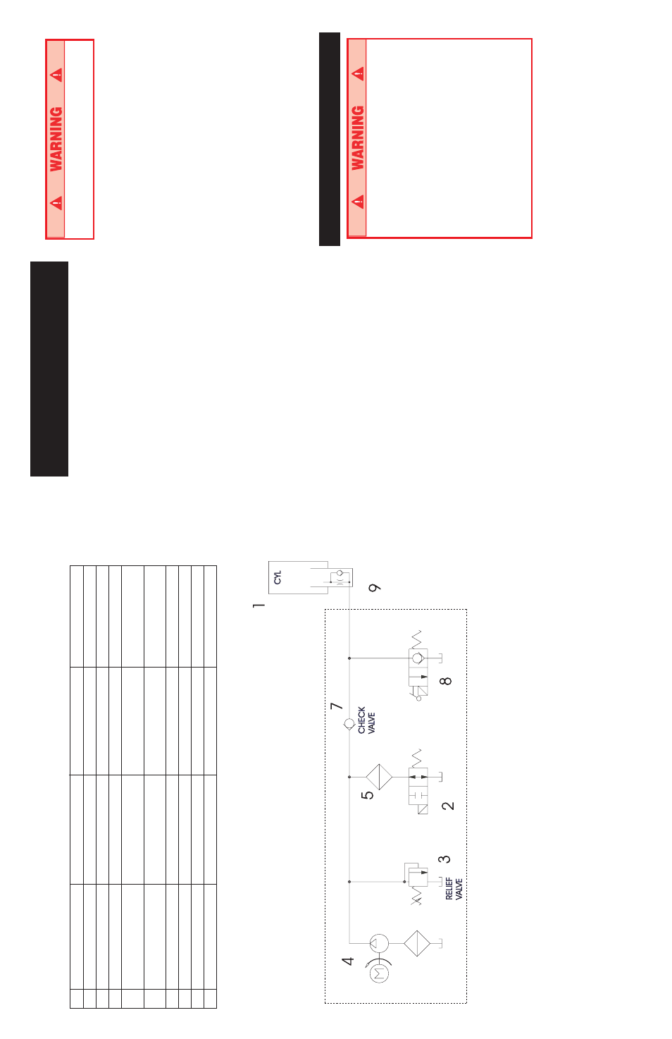
U-Drive 25 Hydraulic Schematic - 068011-000
ENGLISH
FRANCAIS
GERMAN
SPANISH
1
Lift Cylinder
Vérin
de
levage
Hubzylinder
Cilindro
de
elevación
2
Bypass
Valve
Soupape
de
dérivation
Umgehungsventil
Válvula
de
derivación
3
R
elief
Valve
Soupape
de
décharge
Überdruckventil
Válvula de alivio
4
R
eturn
Line
Filter
Filtre
de
canalisation
de
Rücklauffilter
Filtro de la línea
retour
de
retorno
5
M
otor/Pump
Unit
Unité
de
moteur/pompe
Motor-Pumpeneinheit
Unidad
de
la
bomba/motor
6
Tank Filter
Filtre
de
réservoir
Tankfilter
Filtro del depósito
7
Check
Valve
Clapet
de
non-retour
Rückschlagventil
Válvula
de
comprobación
8
Lift
Valve
Soupape
de
levage
Hubventil
Válvula
de
elevación
9
O
rifice
Orifice
Drosselblende
Orificio