Flowmeter, Cal. overview, Bar graph display – Class1 Digital Display User Manual
Page 6
6
Cal. Overview
Display Calibration for Gauges with bargraph displays
The calibration mode is entered by the use of a “password”.
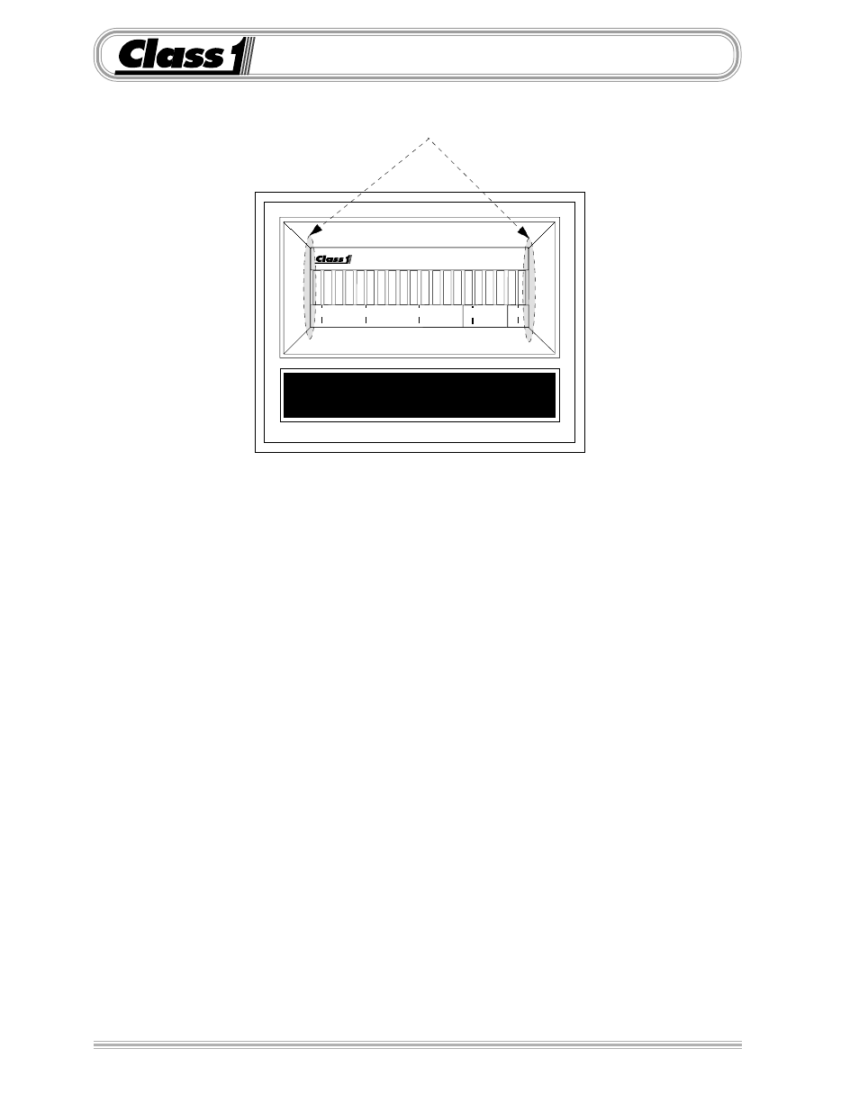
There are two magnetic switches, one located at each side of the display.
These switches are activated with the use of a magnet.
Switch activation is visually confirmed by the toggling of the four closest bars on the
display to the switch. If they are on they will turn off, if they are off they will turn on.
A password will look like the following example.
L L L R R R
Enter the switch sequence with a magnet to enter the basic calibration mode.
Left Switch
Left Switch
Left Switch
Right Switch
Right Switch
Right Switch
If the password is correctly entered, the left-most bar will turn on and flash. This indicates that
the display is ready to be calibrated for the low set point.
With the system adjusted to the minimum calibration point (the system should be empty or at
the lowest pressure condition) activate the left switch and then the right switch.
The right-most bar will begin to flash, indicating the display is ready for the high set point
calibration.
Adjust the system to it’s maximum operating condition. Activate the right switch followed by
the left switch.
The display will return to normal operation and indicate current system status as a percentage
of maximum calibrated capacity.
BAR GRAPH DISPLAY
0 25 50 75 100
Location of magnetic switches