Tank level – Class1 Digital Display User Manual
Page 21
21
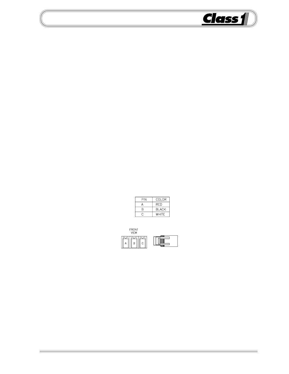
The Tank Level Display is connected to the OEM harness with a Deutsch 8
pin connector.
Mating Connector:
DTM06-08S
Locking Wedge
WM-8S
Mating Terminal:
0462-201-20141 (20 gauge socket)
Terminal Assignments:
1
Alarm OUT
2
Pressure Signal IN
3
5 VDC OUT
4
Display Power (Ignition 12 VDC)
5
System Ground
6
Sensor Ground OUT
7
Secondary pressure IN ( option )
8
Alarm Silence IN
Mount a 3/4 NPT elbow just off the bottom of the tank, enough to keep sedi-
ment out of the elbow and transducer (PN 102162). Attach a 3/4 to 1/4 NPT
adapter (supplied for foam) to the elbow and mount the transducer to that.
The elbow and adapter need to be installed so that the transducer is mounted
vertically.
Pressurized Tanks
If you have a pressurized tank, two pressure transducers (PN 102162) can
be used to compensate for pressure or vacuum in the tank. One transducer
should be mounted near the bottom of the tank and one near the top.
When calibrating the dual transducer installation, the tank should
be vented to the atmosphere.
Tank Level
- 4 output tank level (5 pages)
- Digital Aerial Warning Display (6 pages)
- Digital Air Minder (8 pages)
- Digital Clock (1 page)
- Flowminder 102046 - SSD Digital Flow Meter (9 pages)
- Digital Oxygen Remaining (6 pages)
- Digital Pressure Gauge (6 pages)
- Digital Tank Level Display (5 pages)
- Electrical System Manager (15 pages)
- Electronic Fire Commander (8 pages)
- ENFO III (4 pages)
- ENFO IV - 1 page (1 page)
- ENFO IV (10 pages)
- Engine status center (9 pages)
- Engine status OEM menu (3 pages)
- ES-Key-USM (30 pages)
- ESM3 (14 pages)
- Intelli Tank 4 light driver module (9 pages)
- Intelli Tank level display with drip empty (16 pages)
- Intelli-Tank (15 pages)
- Total System Manager (19 pages)
- Total System Manager (12 pages)
- Vernier Throttle for CAT- new (8 pages)
- Vernier Throttle for CAT (12 pages)
- Vernier Throttle for Cummins (9 pages)
- Digital Pressure Service & Calibration (5 pages)
- 109395 - ITL 4LT with 1-wire COM 106296 106299 - 1page (1 page)
- Throttle Information Reference (24 pages)
- ITL Tank Level Driver Module 107451 (9 pages)
- ITL Mini Remote Driver one-page_manual 112648 (1 page)
- Throttle Interface CAT 105216 (8 pages)
- Pump Throttle Electric Cotnrol Series 2 (14 pages)
- 107490 - UNI-Governor 107396 107269 software v 6 00 (38 pages)
- FoamLogix 2.1A & 1.7AHP REV E (96 pages)
- EZFill Foam Refill (46 pages)
- Digital speedometer (4 pages)
- 106759 - ITL 4LT with 1-wire COM 106296 106299 (18 pages)
- 114356 - ITL 4LT with 1-wire and CAN COM 113739 114378 (24 pages)
- 115355 - ITL 4LT with 1-wire and CAN COM 113739 114378 - Page (1 page)
- 117155 - TPG Governor - 117684 EXTERNAL (30 pages)
- 117155 - TPG Governor - 117685 (2 pages)
- 118253 - ITL40 108404-XX - Full (26 pages)
- 118252 - ITL40 118404-XX - Quick Start (1 page)
- 118712 - TPG+ Governor - 118710 (2 pages)