Infinity supported application 9 – AEM Infinity Supported Applications - Mitsubishi 1995-1999 4G63 Engine User Manual
Page 9
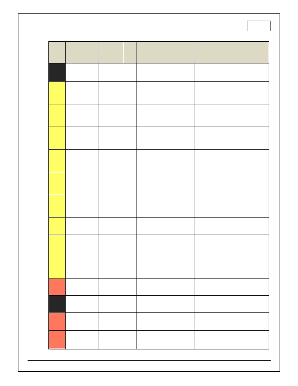
Infinity Supported Application
9
© 2014 AEM Performance Electronics
Infinity
Pin
Hardware
Reference
7100-XXXX-62
7101-XXXX-63
Function
Dest.
Pin
2G
DSM
Hardware Specification
Notes
C1-10
+12V_R8C_CPU
Battery Perm
Power
80
Dedicated power management CPU
Full time battery power. MUST be powered
bef ore the ignition switch input is triggered.
(See C1-65.)
C1-11
Coil 4
Coil 4
25 mA max source current
0–5V Falling edge f ire. DO NOT connect
directly to coil primary . Must use an ignitor
OR CDI that accepts a FALLING edge f ire
signal.
C1-12
Coil 3
Coil 3
25 mA max source current
0–5V Falling edge f ire. DO NOT connect
directly to coil primary . Must use an ignitor
OR CDI that accepts a FALLING edge f ire
signal.
C1-13
Coil 2
Coil 2
23
25 mA max source current
0–5V Falling edge f ire. DO NOT connect
directly to coil primary . Must use an ignitor
OR CDI that accepts a FALLING edge f ire
signal.
C1-14
Coil 1
Coil 1
10
25 mA max source current
0–5V Falling edge f ire. DO NOT connect
directly to coil primary . Must use an ignitor
OR CDI that accepts a FALLING edge f ire
signal.
C1-15
Coil 6
Coil 6
25 mA max source current
0–5V Falling edge f ire. DO NOT connect
directly to coil primary . Must use an ignitor
OR CDI that accepts a FALLING edge f ire
signal.
C1-16
Coil 5
Coil 5
25 mA max source current
0–5V Falling edge f ire. DO NOT connect
directly to coil primary . Must use an ignitor
OR CDI that accepts a FALLING edge f ire
signal.
C1-17
LowsideSwitch_2
Coolant Fan 1
Control
20
Lowside switch, 4A max, NO
internal f ly back diode.
See "LowSide Assignment Tables" f or output
assignment.
C1-18
LowsideSwitch_3
MIL Output
36
Lowside switch, 4A max with
internal f ly back diode. Inductiv e
load should NOT hav e f ull time
power.
See Wizard page "LowSide Assignment
Tables" f or output assignment.
MIL Activ ates when any of the f ollowing f lags
are true: ErrorAirTemp, ErrorBaro,
ErrorCoolantTemp, ErrorEBP,
ErrorFuelPressure, UEGO_0_Diag_error,
UEGO_1_Diag_error, ErrorMAFAnalog,
ErrorMAFDigital, ErrorMAP, ErrorOilPressure,
ErrorThrottle.
C1-19
AGND_1
Sensor
Ground
92
Dedicated analog ground
Analog 0–5V sensor ground
C1-20
AGND_1
Sensor
Ground
Dedicated analog ground
Analog 0–5V sensor ground
C1-21
Crankshaf t
Position Sensor
Hall
Crankshaf t
Position
Sensor Hall
89
10K pullup to 12V. Will work with
ground or f loating switches.
See Setup Wizard page Cam/Crank f or
options.
C1-22
Camshaf t Position
Sensor 1 Hall
Camshaf t
Position
Sensor 1 Hall
88
10K pullup to 12V. Will work with
ground or f loating switches.
See Setup Wizard page Cam/Crank f or
options.