AEM Infinity Supported Applications - Mitsubishi 1995-1999 4G63 Engine User Manual
Page 16
16
© 2014 AEM Performance Electronics
Infinity
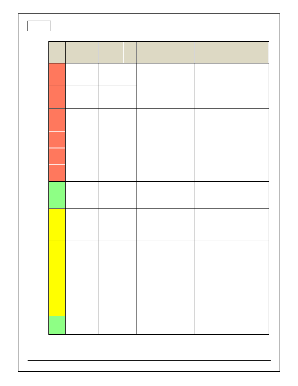
Pin
Hardware
Reference
7100-XXXX-62
7101-XXXX-63
Function
Dest.
Pin
2G
DSM
Hardware Specification
Notes
C2-27
VR-_In_4
Non Driv en
Right Wheel
Speed Sensor
-
Dif f erential Variable Reluctance
Zero Cross Detection
See Non Driv en Wheel Speed Calibration in
the Setup Wizard Input Function Assignment
page.
C2-28
V R+_In_4
Non Driv en
Right Wheel
Speed Sensor
+
C2-29
LowsideSwitch_9
Tachometer
58
Lowside switch, 4A max with
internal f ly back diode, 2.2K 12V
pullup. Inductiv e load should NOT
hav e f ull time power.
See Setup Wizard page Tacho f or
conf iguration options.
C2-30
AGND_2
Sensor
Ground
Dedicated analog ground
Analog 0–5V sensor ground
C2-31
AGND_2
Sensor
Ground
Dedicated analog ground
Analog 0–5V sensor ground
C2-32
AGND_2
Sensor
Ground
Dedicated analog ground
Analog 0–5V sensor ground
C2-33
Analog_In_20
Spare Analog
Input
12 bit A/D, 100K pullup to 5V
0–5V analog signal. Use +5V Out pins as
power supply and Sensor Ground pins as the
low ref erence. Do not connect signals
ref erenced to +12V as this can permanently
damage the ECU.
C2-34
Analog_In_21
3 Step Enable
Switch
12 bit A/D, 100K pullup to 5V
0–5V analog signal. Use +5V Out pins as
power supply and Sensor Ground pins as the
low ref erence. Do not connect signals
ref erenced to +12V as this can permanently
damage the ECU. See 3StepSwitch 1-axis
table f or setup.
C2-35
Analog_In_22
USB Logging
Activ ate
12 bit A/D, 100K pullup to 5V
0–5V analog signal. Use +5V Out pins as
power supply and Sensor Ground pins as the
low ref erence. Do not connect signals
ref erenced to +12V as this can permanently
damage the ECU. See USBLoggingRequestIn
channel f or input state. See Setup Wizard
page USB Logging f or conf iguration options.
C2-36
Analog_In_23
Charge Out
Pressure
12 bit A/D, 100K pullup to 5V
0–5V analog signal. Use +5V Out pins as
power supply and Sensor Ground pins as the
low ref erence. Do not connect signals
ref erenced to +12V as this can permanently
damage the ECU. See ChargeOutPress [kPa]
channel f or input state. See Setup Wizard
page Charge Out Pressure f or calibration
options.
C2-37
Digital_In_6
Spare Digital
Input
45
No pullup. Will work with TTL
signals.
Input can be assigned to dif f erent pins. See
Setup Wizard page Input Function
Assignments f or input mapping options.