Wire view of aem ems – AEM 30-6600 Series 2 Plug & Play EMS User Manual
Page 9
Connection Diagram for EMS P/N 30-6600
Pin
1989-1994 Nissan 240SX S14 KA24DE
1991-1994 Nissan Sentra B13 GA16DE
1990-1994 Nissan Pulsar GTi-R N14 SR20DET
1991-1993 Nissan NX B13 GA16DE
1993-1994 Nissan Altima U13 KA24DE
1989-1995 Nissan Bluebird U13 SR20DET
1991-1993 Infiniti G20 P10 SR20DE
AEM EMS 30-
6600
I/O
Notes
15
Data Link Connector
EGT 2
Input
Available, jumper set for 0-5V input
16
Mass Air Flow Sensor
MAF
Input
PnP for MAF Sensor
17
Mass Air Flow Ground
Power Ground
Input
Dedicated
18
Engine Coolant Temperature Sensor
Coolant
Input
PnP for Coolant Temp Sensor
19
Oxygen Sensor
O2 #1
Input
Dedicated, 0-5V input signal
20
Throttle Position Sensor
TPS
Input
PnP for Throttle Position Sensor
21
Sensor Ground
Sensor Ground
Output
Dedicated
22
Crankshaft Reference Signal
Cam (T2)
Input
Dedicated, must use AEM replacement trigger disc.
Connects to pin 30
23
Diagnostics check (SR20 only)
Injector 5
Output
Available, Switched Ground, 1.5A Max
24
Malfunction Indicator Light
Low Side 10
Output
Available, Switched Ground, 1.5A Max
25
Swirl Control Valve (91-94 240SX only)
Coil 4
Output
Available Coil 4, 0-5V falling edge trigger
26
Air Temp Sensor (Late 89 and all 90 240SX)
AIT
Input
Available, AIT Sensor Input
27
Knock Sensor (Except 89-90 240SX & 1.6L)
Knock 1
Input
PnP for Knock Sensor
28
Throttle Signal Output (A/T only)
High Side 1
Output
Available, Switched +12V, 1.5A Max
29
Sensor Ground
Sensor Ground
Output
Dedicated
30
Crankshaft Reference Signal
Cam (T2)
Input
Dedicated, must use AEM replacement trigger disc.
Connects to pin 22
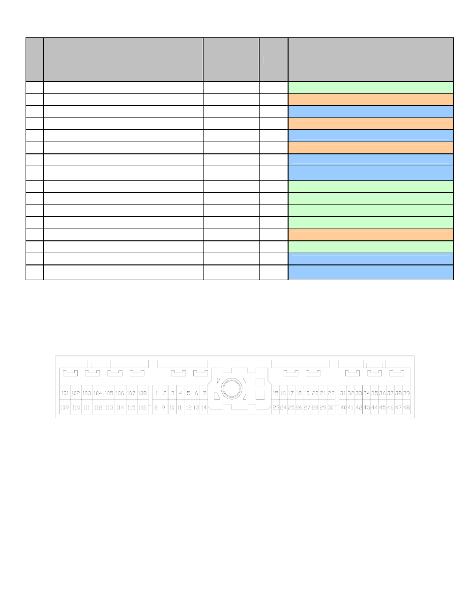
Wire View of AEM EMS
Page 9 of 12