6) ready to begin tuning the vehicle – AEM 30-6600 Series 2 Plug & Play EMS User Manual
Page 4
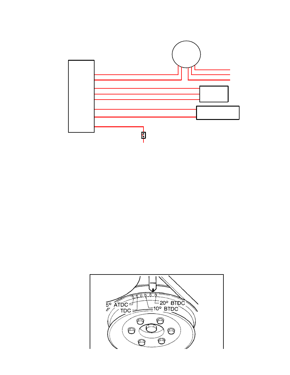
5) Wiring accessories to the EMS:
Please follow this suggested wiring diagram when adding accessories such as UEGO
gauges, MAP sensors, IAT sensors, or switches for use with the EMS. Note that wire
polarity is not important for the Air Temperature sensor.
+5V Sensor Power
Switched Input
41
Sensor Ground
IAT Sensor
29
26
AEM EMS
P/N: 30-6600
Sensor Ground
MAP Signal
35
29
37
Sensor Ground
O2 Sensor 1
19
29
Ground
Switch 6
Air Temperature Sensor
P/N: 30-2010
Black (Sensor Ground)
Green (MAP Signal)
Red (+5V Sensor Power)
Black (Battery or chassis ground)
Red (+12V power, 5A fuse)
AEM UEGO
P/N: 30-5130
Brown (Analog - signal)
White (0-5V Analog + signal)
Pink (Switched +12V Power)
MAP Sensor
P/N: 30-2130-50
6) Ready to begin tuning the vehicle.
a)
Before starting the engine, verify that the fuel pump runs for a couple of seconds
when the key is turned on and there is sufficient pressure at the fuel rail.
If a MAP sensor is installed, check that the Engine Load indicates something near
atmospheric pressure (approximately 101kPa or 0 PSI at sea level) with the key on
and engine off. Press the throttle and verify that the ‘Throttle’ channel responds but
the Engine Load channel continues to measure atmospheric pressure correctly.
b)
Start the engine and make whatever adjustments may be needed to sustain a safe
and reasonably smooth idle. Verify the ignition timing: Select Wizards>>Ignition
Timing Sync from the pull-down menu. Click the ‘Lock Ignition Timing’ checkbox
and set the timing to a safe and convenient value (for instance, 10 degrees BTDC).
Use a timing light and compare the physical timing numbers to the timing value you
selected. Use the Sync Adjustment Increase/Decrease buttons to make the
physical reading match the timing number you selected.
Crankshaft timing marks are not labeled for some vehicles. Consult the factory
service manual for more information. The diagram below shows marks for the
240SX:
Page 4 of 12