Wire view of aem ems – AEM 30-6600 Series 2 Plug & Play EMS User Manual
Page 8
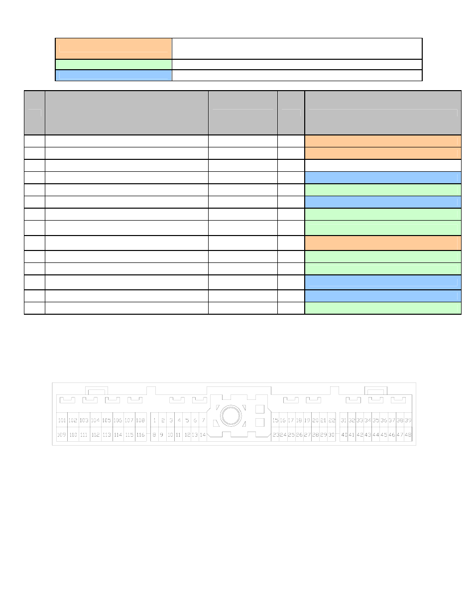
Connection Diagram for EMS P/N 30-6600
PnP
Means the Plug and Play system comes with this configured for proper operation of this
device. Is still available for reassignment by the end user.
Available
Means the function is not currently allocated and is available for use
Dedicated
Means the location is fixed and cant be changed
Pin
1989-1994 Nissan 240SX S14 KA24DE
1991-1994 Nissan Sentra B13 GA16DE
1990-1994 Nissan Pulsar GTi-R N14 SR20DET
1991-1993 Nissan NX B13 GA16DE
1993-1994 Nissan Altima U13 KA24DE
1989-1995 Nissan Bluebird U13 SR20DET
1991-1993 Infiniti G20 P10 SR20DE
AEM EMS 30-6600
I/O
Notes
1
Ignition Signal
Coil 1
Output
PnP for Coil 1, 0-5V falling edge trigger
2
Tachometer Signal
Low Side 7
Output
PnP for Tachometer
3
Ignition Check
--- ---
Not Used
4
ECCS Relay control, Ignition Relay control
Main Relay (control)
Output
Dedicated, EMS activates relay with switched GND
5
--- Coil
3
Output
Available Coil 3, 0-5V falling edge trigger
6
ECCS Ground
Power Ground
Input
Dedicated
7
Data Link Connector
Coil 2
Output
Available Coil 2, 0-5V falling edge trigger
8
EGR Sensor (Except 89-90 Non CA 240SX and
SR20DET)
EGT 1
Input
Available, jumper set for 0-5V Input
9
Cooling Fan Relay
Low Side 3
+ Low Side 12
Output
PnP for Cooling Fan,
can be activated by LS3 or LS12 output
10
Cooling Fan High Speed (A/T 2.0L only)
Low Side 5
Output
Available, Switched Ground, 1.5A max
11
Air Conditioner Relay
Low Side 6
Output
Available, Switched Ground, 1.5A max
12
Swirl Control Valve (89-90 240SX Only)/VTC Solenoid
(1.6L only)
CAN1H Input
Dedicated. CAN high side
13
ECCS Ground
Power Ground
Input
Dedicated
14
Diagnostics Clock
Injector 7
Output
Available, Switched Ground, 1.5A Max
Wire View of AEM EMS
Page 8 of 12