AEM 30-6310 Series 2 Plug & Play EMS User Manual
Page 5
Page 5 of 15
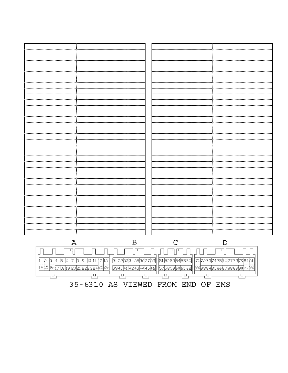
Application Notes for EMS P/N 30-6310
1995-1999 Eclipse Turbo / Eagle Talon Tsi
2003-2005 Lancer Evolution VIII
Make:
Mitsubishi/Dodge
Spare Injector Drivers:
Inj 7, Pin 116
Model:
Eclipse Turbo / Talon Tsi /
EVO VIII
Spare Injector Drivers:
Inj 8, Pin 6
Years Covered:
1995 – 1999 Eclipse Turbo /
Talon, 2003-2005 EVO8
Spare Injector Drivers:
Inj 9, Pin 83
Engine Displacement:
2.0L
Spare Injector Drivers:
Inj 10, Pin 105
Engine Configuration:
I4
Spare Injector Drivers:
Inj 11, Pin 89
Firing Order:
1-3-4-2
Spare Injector Drivers:
Inj 12, Pin 104
N/A, S/C or T/C:
Turbocharged
Load Sensor Type:
Karman Vortex MAF
Spare Coil Drivers:
Coil 4, Pin 91
# Coils:
2 (wasted spark)
Spare Coil Drivers:
Coil 5, Pin 82
Ignition driver type:
0-5V, Falling Edge trigger
Spare Coil Drivers:
Coil 6, Pin 85
# Injectors:
4 (P&H drivers: Inj1-4)
Boost Solenoid:
PW 2, Pin 102
Injector Flow Rate:
450 cc/min
EGT 1 Location:
Pin 54
Injector Resistance:
2.5 Ω
EGT 2 Location:
Pin 90
Factory Inj Resistors:
Yes (6 Ω)
EGT 3 Location:
Pin 112
Injection Mode:
Sequential
EGT 4 Location:
Pin 111
Knock Sensors used:
1
Spare 0-5V Channels:
MAF, Pin 59
Lambda Sensors
used:
1 (aftermarket wideband:
Spare 0-5V Channels:
ADCR12, Pin 65
factory O2 not supported)
Spare Low Side Driver:
Low Side 1, Pin 109
Idle Motor Type:
Stepper
Spare Low Side Driver:
Low Side 2, Pin 21
Main Relay Control:
Yes (Switch1 in, Coil7 out)
Spare Low Side Driver:
Low Side 3, Pin 71
Crank Pickup Type:
Hall
Spare Low Side Driver:
Low Side 4, Pin 9
Crank Teeth/Cycle:
4
Spare Low Side Driver:
Low Side 5, Pin 90
Cam Pickup Type:
Hall
Spare Low Side Driver:
Low Side 9, Pin 20
Cam Teeth/Cycle:
2
Check Engine Light:
Low Side 10, Pin 106
Transmissions
Offered:
M/T, A/T
Spare Switch Input:
Switch 3, Pin 24
Trans Supported:
M/T Only
Spare Switch Input:
Switch 4, Pin 7
Drive Options:
FWD, AWD
Spare Switch Input:
Switch 5, Pin 107
Supplied Connectors:
Connector B, spare pins
Spare Switch Input:
Switch 6, Pin 114
Plug-N-Pin kit:
AEM part# 35-2611
A/C Switch Input:
Switch 2, Pin 115
(includes plugs A-D, pins)
Clutch Switch Input:
---
WARNING:
* The factory A/C request switch sends 12V power to signal an A/C request and the 30-
6310 EMS has been designed to accept 12V power on this switched input. If users desire
to re-wire a new switch to trigger the Switch 2 input the switch should connect to 12V
power when the switch is on. The pin can be left floating (disconnected) when the switch is
off; it is not required to send ground to this pin.