AEM 30-6310 Series 2 Plug & Play EMS User Manual
Page 11
Page 11 of 15
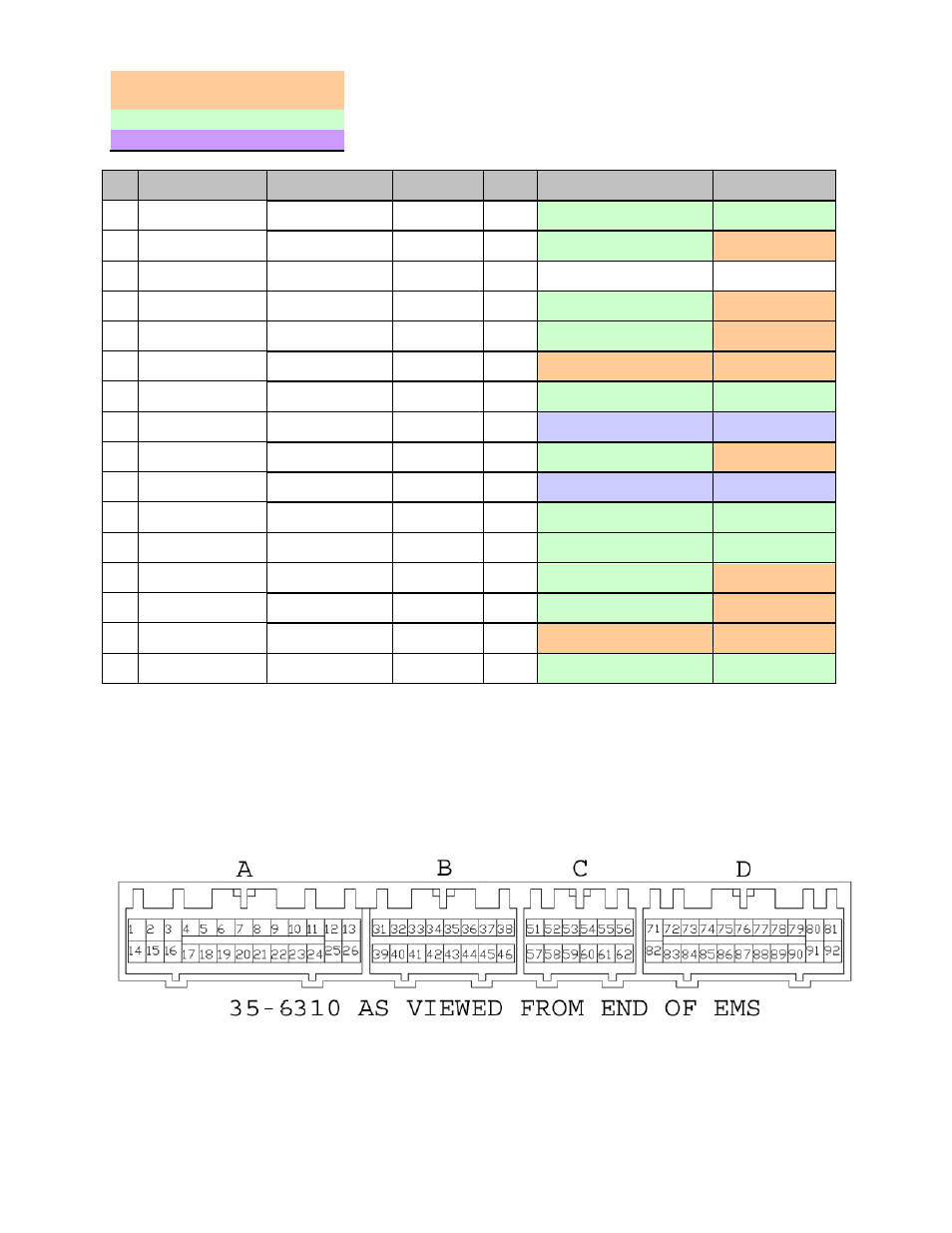
Connection Diagram for EMS P/N 30-6310
PnP
Means the Plug and Play system comes with this configured for proper operation of this
device. Is still available for reassignment by the end user.
Avail
Means the function is not currently allocated and is available for use
Dedicated
Means the location is fixed and cant be changed
Pin
95 - 99 Eclipse
Turbo / Talon Tsi
2003-2005 Evo VIII
AEM EMS
30-6310
I/O
95 - 99 Eclipse/Talon
Notes
2003-2005 Evo
VIII Notes
31
---
<--
Idle 8
Output
Avail, Ground / +12V, 1.5A
max
<--
32
---
Condenser Fan
Relay (HIGH)
Idle 5
Output
Avail, Ground / +12V, 1.5A
max
PnP for Fan
Control
33
Voltage Regulator
G
<--
Not Used
---
---
---
34
---
Condenser Fan
Relay (LOW)
Injector 12
Output
Avail, Inj output 1.5A max
(not P&H)
PnP for Fan
Control
35
---
H2O Spray LED
Injector 10
Output
Avail, Inj output 1.5A max
(not P&H)
PnP for H2O
Spray
36
Check Engine Light
Lamp: “Service
Engine Soon”
Low Side 10
Output
PnP for 7,000 RPM Shift
Light
<--
37
PS Press. Switch
<--
Switch 5
Input
Avail, switch must connect
to ground
<--
38
MFI Relay
<--
Main Relay
(Coil7)
Output
Dedicated, EMS activates
relay with switched GND
<--
39
---
Fuel Pump Low
Speed Relay
Low Side 1
Output
Avail, Switched Ground
driver
PnP for Fuel Pump
Low Speed Relay
40
---
MAF Ground
Sensor
Ground
Output
Dedicated, sensors only
Dedicated,
sensors only
41
Voltage Regulator
FR
<--
EGT4
(ADCR16)
Input
Avail, jumper set for 0-5V
Input
<--
42
---
<--
EGT3
(ADCR15)
Input
Avail, jumper set for 0-5V
Input
<--
43
---
Clutch Pedal Sw
Switch 4
Input
Avail, switch must connect
to ground
PnP for Clutch
switch
44
---
H2O Spray Auto
Switch
Switch 6
Input
Avail, switch must connect
to ground
PnP for H2O
Spray
45
Automatic
Compressor ECM
<--
Switch 2
Input
PnP for A/C request switch
<--
46
---
<--
Injector 7
Output
Avail, Inj output 1.5A max
(not P&H)
<--