AEM 30-6310 Series 2 Plug & Play EMS User Manual
Page 10
Page 10 of 15
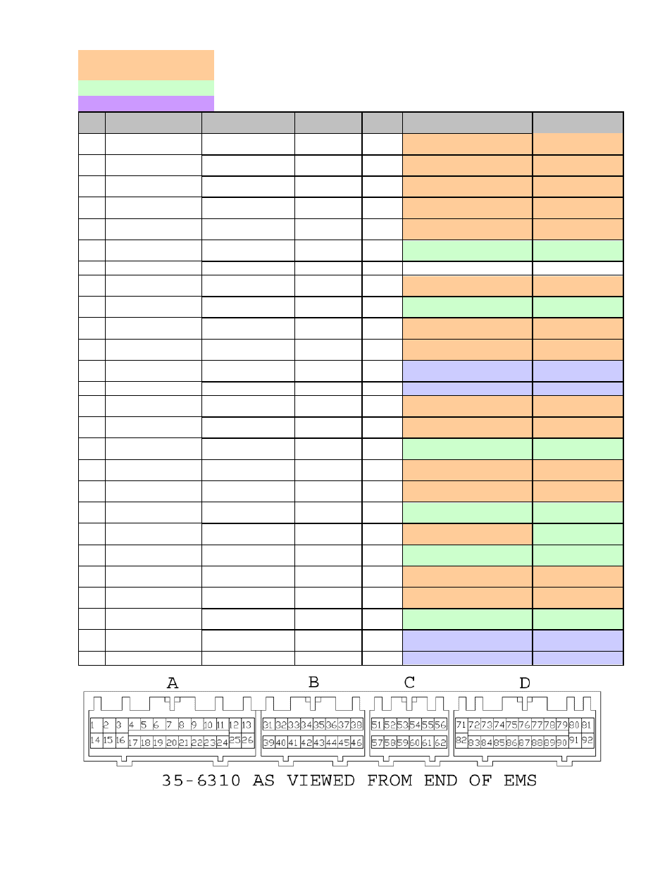
Connection Diagram for EMS P/N 30-6310
PnP
Means the Plug and Play system comes with this configured for proper operation of this device. Is
still available for reassignment by the end user.
Avail
Means the function is not currently allocated and is available for use
Dedicated
Means the location is fixed and cant be changed
Pin
95 - 99 Eclipse
Turbo / Talon Tsi
2003-2005 Evo VIII
AEM EMS
30-6310
I/O
95 - 99 Eclipse/Talon Notes
2003-2005 Evo VIII
Notes
1
Injector 1
<--
Injector 1
P&H
Output
Injector 1 (Peak/Hold 4A/1A
driver)
<--
2
Injector 3
<--
Injector 3
P&H
Output
Injector 3 (Peak/Hold 4A/1A
driver)
<--
3
Fuel Pressure
Solenoid
<--
Injector 5
P&H
Output
Injector 5 (Peak/Hold 4A/1A
driver)
<--
4
Idle Speed Control
Servo (pin 1)
Idle Speed Control
Servo (A1)
Idle 1
Output
PnP for Stepper Idle Motor
<--
5
Idle Speed Control
Servo (pin 4)
Idle Speed Control
Servo (B1)
Idle 3
Output
PnP for Stepper Idle Motor
<--
6
EGR Solenoid Valve
<--
Injector 8
Output
Avail, Inj output 1.5A max (not
P&H)
<--
7
---
---
Not Used
---
---
---
8
MFI Relay (fuel
pump)
Magnetic Clutch
Relay
Low Side 11
Output
PnP for Fuel Pump relay
PnP for A/C
Compressor Relay
9
EVAP Purge
Solenoid Valve
<--
Low Side 4
Output
Avail, Switched Ground, 1.5A
max
<--
10
Ignition Power
Transistor (1&4)
<--
Coil 1
Output
PnP for Coil 1, rising edge
trigger
<--
11
Wastegate Solenoid
Valve
<--
PW 2
Output
PnP for Wastegate Control
Solenoid
<--
12
MFI Relay Power IN
(main)
<--
+12V
Switched
Input
Dedicated, +12V when relay
is on
<--
13
Ground
<--
Ground
Input
Dedicated
<--
14
Injector 2
<--
Injector 2
P&H
Output
Injector 2 (Peak/Hold 4A/1A
driver)
<--
15
Injector 4
<--
Injector 4
P&H
Output
Injector 4 (Peak/Hold 4A/1A
driver)
<--
16
Boost Gauge
---
Injector 6
P&H
Output
Available, Injector 6
(Peak/Hold 4A/1A driver)
<--
17
Idle Speed Control
Servo (pin 3)
Idle Speed Control
Servo (A2)
Idle 2
Output
PnP for Stepper Idle Motor
<--
18
Idle Speed Control
Servo (pin 6)
Idle Speed Control
Servo (B2)
Idle 4
Output
PnP for Stepper Idle Motor
<--
19
MAF reset switch
<--
Low Side 8
Output
Avail, Switched Ground, 1.5A
max
<--
20
Radiator/Condensor
Fan Relay HI, LO2
---
Low Side 9
Output
PnP for Fan Control
Avail, Switched
Ground, 1.5A max
21
Radiator Fan Relay
LO1
Cooling Fan Control
signal
Low Side 2
Output
Avail, Switched Ground, 1.5A
max
PnP, User 1 PW
output (coolant)
22
Magnetic Clutch
Relay
MFI Relay (Fuel
Pump)
Low Side 6
Output
PnP for A/C Compressor
PnP for Fuel Pump
relay
23
Ignition Power
Transistor (2&4)
<--
Coil 2
Output
PnP for Coil 2, rising edge
trigger
<--
24
---
<--
Switch 3
Input
Avail, switch must connect to
ground
<--
25
MFI Relay Switched
Power
<--
+12V
Switched
Input
Dedicated, +12V when relay
is on
<--
26
Ground
<--
Ground
Input
Dedicated
<--