AEM 30-6310 Series 2 Plug & Play EMS User Manual
Page 12
Page 12 of 15
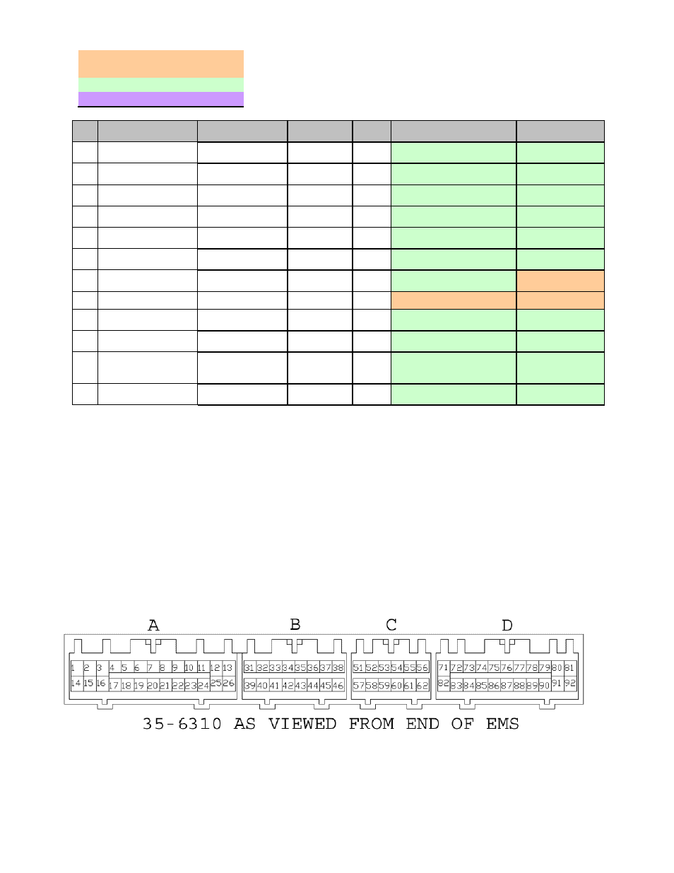
Connection Diagram for EMS P/N 30-6310
PnP
Means the Plug and Play system comes with this configured for proper operation of this
device. Is still available for reassignment by the end user.
Avail
Means the function is not currently allocated and is available for use
Dedicated
Means the location is fixed and cant be changed
Pin
95 - 99 Eclipse
Turbo / Talon Tsi
2003-2005 Evo VIII
AEM EMS
30-6310
I/O
95 - 99 Eclipse/Talon Notes
2003-2005 Evo
VIII Notes
51
---
Immobilizer System
Low Side 3
Output
Avail, Switched Ground
driver
<--
52
Ignition Timing Adj.
Connector
---
Coil 3
Output
Avail, Switched Ground,
1.5A max
Avail, Switched
Ground, 1.5A max
53
---
<--
Coil 5
Output
Avail, Switched Ground,
1.5A max
<--
54
O2 Heater Rear
<--
Injector 9
Output
Avail, Switched Ground,
1.5A max
<--
55
Evap. Vent Solenoid
Valve (99 Only)
Evap. Vent
Solenoid Valve
Low Side 5
Output
Avail, Inj output 1.5A max
(not P&H)
<--
56
Data Link Connector
---
Coil 6
Output
Avail, Switched Ground,
1.5A max
<--
57
---
H2O Spray Relay
Idle 7
Output
Avail, Ground / +12V, 1.5A
max
PnP for H2O Spray
58
Tacho
<--
Low Side 7
Output
PnP for Tacho
PnP for Tacho
59
---
<--
Low Side 12
Output
Avail, Switched Ground
driver
60
O2 Heater Front
<--
Injector 11
Output
Avail, Switched Ground,
1.5A max
<--
61
Fuel Tank Differ.
Pressure Sensor (99
Only)
Fuel Tank Differ.
Pressure Sensor
EGT2
Input
Avail, Inj output 1.5A max
(not P&H)
<--
62
Data Link Connector
<--
Coil 4
Output
Avail, jumper set for 0-5V
Input
<--