Pinouts, Infinity pinout – AEM 30-3508 Infinity Plug & Play Harnesses - Honda 2000-2005 S2000 User Manual
Page 9
2000–2005 Honda S2000
9
© 2014 AEM Performance Electronics
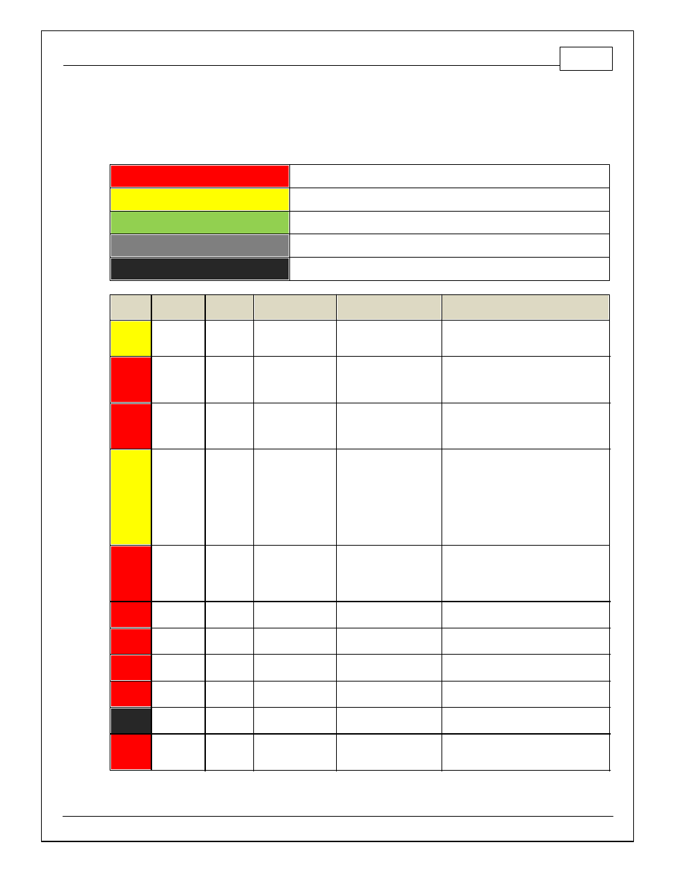
PINOUTS
Infinity Pinout
Dedicated
Dedicated and not reconfigurable
Assigned
Assigned but reconfigurable
Available
Available for user setup
Not Applicable
Not used in this configuration
Required
Required for proper function
Infinity
Pin
Infinity
Assignment
Honda Pin
Honda Description
Infinity Hardware
Specification
Notes
1
LS 4
A17
A/C Clutch Relay
Lowside switch, 4A max, No
internal f ly back diode.
See Setup Wizard Page "LowSide Assignment
Tables" f or output assignment and 2D table
"LS4_Duty [%]" f or on/of f activ ation.
2
LS 5
A19
Engine Speed Pulse
Lowside switch, 4A max
with internal f ly back diode.
Inductiv e load should NOT
hav e f ull time power.
The tachometer is pre-calibrated using a
combination of the LS5_Freq [Hz] 1-axis table
and the LS5_Duty [%] 2-axis table.
3
LS 6
A1
Engine Coolant Temp
Gauge
Lowside switch, 4A max
with internal f ly back diode.
Inductiv e load should NOT
hav e f ull time power.
The coolant temp gauge is pre-calibrated using
the LS6_Freq [Hz] 1-axis table and the
LS6_Duty [%] 2-axis table. This signal is
pulled up to 5V.
4
LS 7
A18
Malf unction Indicator
Light
Lowside switch, 4A max, No
internal f ly back diode.
See Wizard page "LowSide Assignment
Tables" f or output assignment and 2D table
"LS3_Duty [%]" f or activ ation. MIL Activ ates
when any of the f ollowing f lags are true:
ErrorAirTemp, ErrorBaro, ErrorCoolantTemp,
ErrorEBP, ErrorFuelPressure,
UEGO_0_Diag_error, UEGO_1_Diag_error,
ErrorMAFAnalog, ErrorMAFDigital, ErrorMAP,
ErrorOilPressure, ErrorThrottle.
5
UEGO1 Heat
---
---
Bosch UEGO controller
Lowside switch f or UEGO heater control.
Connect to pin 4 of Bosch UEGO sensor.
NOTE that pin 3 of the Sensor is heater (+)
and must be power by a f used/switched 12V
supply .
6
UEGO1 IA
---
---
Bosch UEGO controller
Trim Current signal. Connect to pin 2 of
Bosch UEGO sensor
7
UEGO1 IP
---
---
Bosch UEGO controller
Pumping Current signal. Connect to pin 6 of
Bosch UEGO sensor
8
UEGO1 UN
---
---
Bosch UEGO controller
Nernst Voltage signal. Connect to pin 1 of
Bosch UEGO sensor
9
UEGO1 VM
---
---
Bosch UEGO controller
Virtual Ground signal. Connect to pin 5 of
Bosch UEGO sensor.
10
+12V Perm
Power
B21
Voltage Back Up
Dedicated power
management CPU
Full time battery power. MUST be powered
bef ore the ignition switch input is triggered.
11
Coil 4
C14
Ignition Coil Pulse
No. 4
25 mA max source current
0–5V f alling edge f ire. Do NOT connect
directly to coil primary . Must use an ignitor or
CDI that accepts a f alling edge f ire signal.