AEM 30-3508 Infinity Plug & Play Harnesses - Honda 2000-2005 S2000 User Manual
Page 11
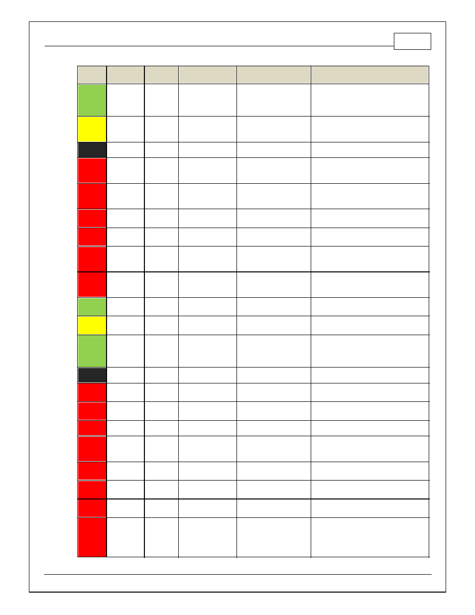
2000–2005 Honda S2000
11
© 2014 AEM Performance Electronics
Infinity
Pin
Infinity
Assignment
Honda Pin
Honda Description
Infinity Hardware
Specification
Notes
31
Digital 6 -
---
---
10K pullup to 12V. Will work
with ground or f loating
switches.
Found on the Aux Connector. Input can be
assigned to dif f erent pins. See Setup Wizard
page Input Function Assignments f or input
mapping options.
32
Digital 7 -
A32
Brake Switch Signal
10K pullup to 12V. Will work
with ground or f loating
switches.
Input can be assigned to dif f erent pins. See
Setup Wizard page Input Function
Assignments f or input mapping options.
33
GND
B2
Power Ground 1
Power Ground
Connects to chassis ground and AEMNet
34
CAN A -
---
---
Dedicated High Speed CAN
Transceiv er
4P DTM Connector f ound in AEM adapter
harness. Contact AEM f or additional
inf ormation.
35
CAN A +
---
---
Dedicated High Speed CAN
Transceiv er
4P DTM Connector f ound in AEM adapter
harness. Contact AEM f or additional
inf ormation.
36
CAN B -
---
---
Dedicated High Speed CAN
Transceiv er
Not used
37
CAN B +
---
---
Dedicated High Speed CAN
Transceiv er
Not used
38
Temp 1 -
Coolant
Temp
C26
Engine Coolant Temp
Sensor
12 bit A/D, 2.49K pullup to
5V
See "Coolant Temperature" Setup Wizard f or
selection.
39
Temp 2 - Air
Temp
(Manif old)
C25
Intake Air Temp
Sensor
12 bit A/D, 2.49K pullup to
5V
See "Air Temperature" Setup Wizard f or
selection.
40
Temp 3 - Oil
Temp
---
---
12 bit A/D, 2.49K pullup to
5V
Found on the Aux Connector. 0–5V analog
signal
41
LS 0
A15
Fuel Pump Relay
Lowside switch, 4A max, No
internal f ly back diode.
Switched ground. Will prime f or 2 seconds at
key on and activ ate if RPM > 0.
42
LS 1
---
---
Lowside switch, 4A max
with internal f ly back diode.
Inductiv e load should NOT
hav e f ull time power.
Found in Aux Connector. See Setup Wizard
page Boost Control f or options. Monitor
BoostControl [%] channel f or output state.
43
GND
B10
Power Ground 2
Power Ground
Connect directly to battery ground.
44
Knock 0
C22
Knock Sensor
Dedicated knock signal
processor
See Knock in Setup Wizard f or options.
45
Knock 1
Dedicated knock signal
processor
See Knock in Setup Wizard f or options.
46
GND
B20
Logic Ground 1
Power Ground
Connect directly to battery ground.
47
12V_Relay _
Control
---
---
0.7A max ground sink f or
external relay control
Connects to relay f ound in AEM adapter. Will
activ ate at key ON and at key OFF according
to the conf iguration settings.
48
+12V SW
(Ign Switch)
B1
Power Source 1
10K pulldown
Full time battery power must be av ailable at
inf inity pin 10 bef ore this input is triggered.
49
+5V_Out
C19
Sensor Voltage 1
Regulated, f used +5V
supply f or sensor power
Analog sensor power
50
+5V_Out
C28
Sensor Voltage 2
Regulated, f used +5V
supply f or sensor power
Analog sensor power and f ound on auxiliary
connector
51
Ana7 -
Throttle
C27
Throttle Position
Sensor
12 bit A/D, 100K pullup to
5V
0–5V analog signal. Do not connect signals
ref erenced to +12V as this can permanently
damage the ECU. See the Setup Wizard Set
Throttle Range page f or automatic min/max
calibration.