IDEX Health & Science MCP Standard User Manual
Page 33
MCP Standard/ISMATEC SA/12.06.07/CB/GP
33
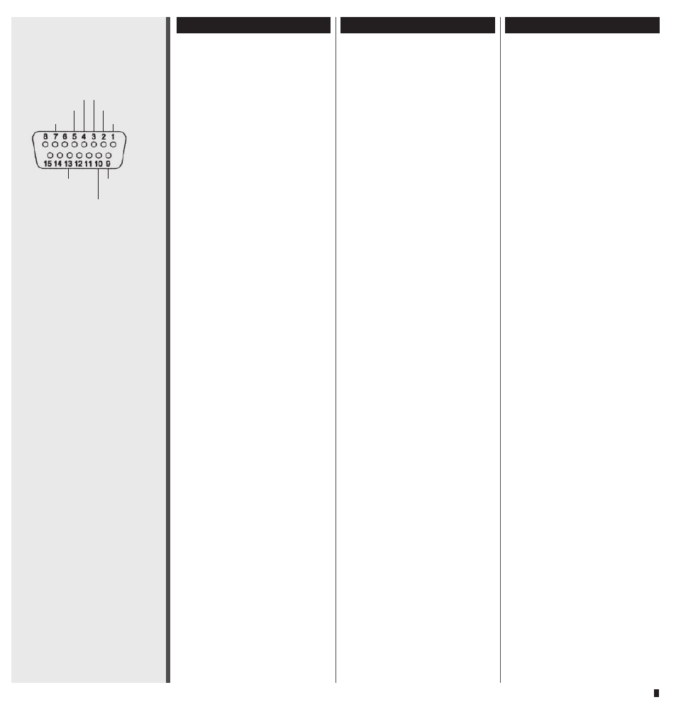
Analog interface
Pin 1, GND (ground)
Reference potential for all other
inputs
Pin 2, local / remote
For changing between manual
control and analog interface. For
activating the analog interface,
pin 2 must be connected with pin
1 (GND).
Pin 3, stop / run
In remote operation (pin 2 to
GND) the pump starts when con-
nected to pin 1 (GND)
Pin 4, direction
In the open position the pump
turns clockwise; when connected
to pin 1 (GND) it turns counter-
clockwise.
Pin 5, speed IN
External speed control (0 – 5 V,
0 – 10 V, 0 – 20 mA, 4 – 20 mA)
Input impedance and input range
can be selected via a dip-switch
inside the pump (see page 35)
Pin 7, +36V
DC
About +36 V
DC
are available (max.
current 1A).
*
)
*
) The max. total current of the
+36 V
DC
supply on pin 7 and on
pin 9 and 10 of the valve interface
is 1 A. Fuse: 1.6 A fast, located on
controller board, see diagram on
page 36.
Interface analogique
Pin 1, GND (masse)
Potentiel de référence pour toutes
les autres entrées
Pin 2, local / remote
Pour commuter du service manuel
à l’interface analogique.
Pour activer l'interface analo-
gique, le pin 2 doit être connecté
au pin 1 (GND).
Pin 3, stop / run
En exploitation à distance (pin 2
sur GND), la pompe se met en
route dès qu’elle est connectée au
pin 1 (GND)
Pin 4, direction
Si ouvert, le sens de rotation de
la pompe est celui des aiguilles
d’une montre; si relié avec le pin
1 (GND), elle tourne dans le sens
contraire des aiguilles d’une montre.
Pin 5, speed IN
Réglage externe du nombre de
tours (0 – 5 V, 0 – 10 V,
0 – 20 mA, 4 – 20 mA) Impé-
dance d‘entrée et réglage de zone
au moyen de l’interrupteur DIP à
l’intérieur de l’appareil (v.p. 34)
Pin 7, +36V
CC
Environ +36 V
CC
sont à dispositi-
on (courant maximal 1A).
*
)
*
) Le courant max. de l’alimenta-
tion +36 V
CC
sur le pin 7 et le pin
9 et 10 de l’interface pour valve
est de 1 A. Fusible: 1.6 A rapide,
situé sur la carte contrôleur, voir
schéma en page 36.
Digitale Eingänge (TTL-Pegel)
Digital inputs (TTL-level)
Entrées numériques (niveau TTL)
Pin 2, local / remote
Pin 3, stop / run
Pin 4, direction
Pin 13, speed IN
Analoge Eingänge
Analog inputs
Entrées analogiques
Pin 5, speed IN
0 – 5 V
DC
/ 0 – 10 V
DC
0 – 20 mA / 4 – 20 mA
Analog Ausgang
Analog output
Sortie analogique
Pin 9, motor speed
0 – 10 V
DC
/ 0 – 12 kHz
Analogschnittstelle
Pin 1, GND (Masse)
Bezugspotential für alle anderen
Eingänge.
Pin 2, local / remote
Für Umschaltung zwischen ma-
nueller Bedienung und der Ana-
logschnittstelle. Zur Aktivierung
der Analog-Schnittstelle muss
Pin 2 mit Pin 1 (GND) verbunden
werden.
Pin 3, stop / run
Im Remote-Betrieb (Pin 2 auf
GND) startet die Pumpe bei Ver-
bindung mit Pin 1 (GND)
Pin 4, direction
Wenn offen, dreht die Pumpe
im Uhrzeigersinn; wenn mit Pin
1 (GND) verbunden, dreht sie im
Gegenuhrzeigersinn
Pin 5, speed IN
Externe Drehzahlsteuerung
(0 – 5 V, 0 – 10 V, 0 – 20 mA,
4 – 20 mA)
Eingangsimpedanz und Wahl-
möglichkeiten mittels DIP-Switch
im Geräteinnern (siehe Seite 35)
Pin 7, +36V
DC
Es stehen ca. +36 V
DC
zur Verfü-
gung (max. Strom 1A).
*
)
*
) Der max. Gesamtstrom der +36
V
DC
-Versorgung auf Pin 7 sowie
Pin 9 und 10 der Ventilschnittstel-
le beträgt 1 A. Sicherung: 1.6 AF
auf Steuerprint,
siehe Skizze auf
Seite 36.
GND
+36 V
DC
speed pin 5
internal
motor speed
direction stop / run
local / remote
speed IN
+5 V
DC