Brother HL-1040 User Manual
Page 90
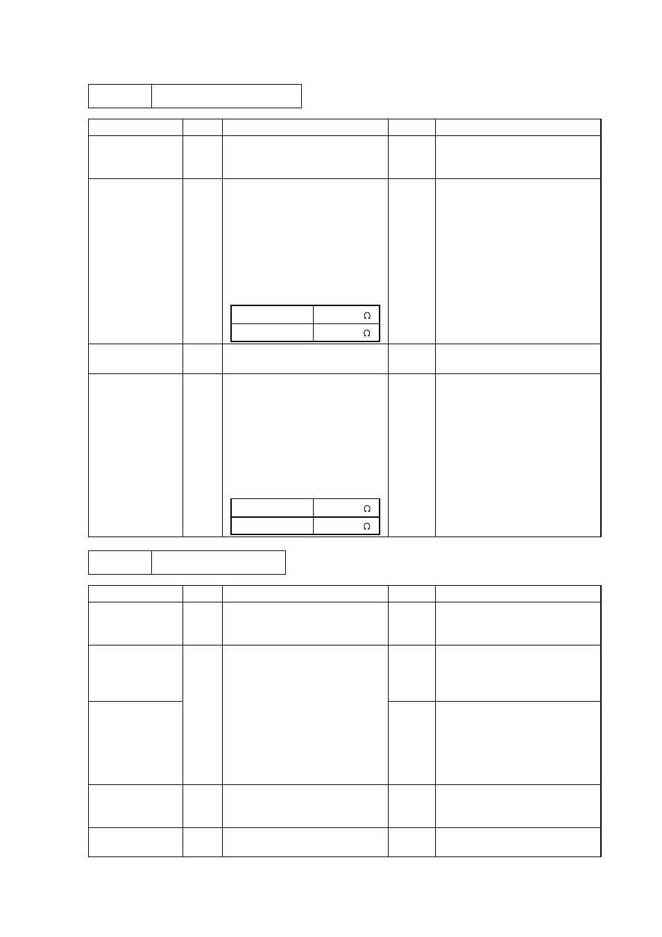
IV-23
M-3
Main motor unrotated
Possible cause
Step
Check
Result
Remedy
Failure of
connector
1
Is the connection of connector
P9 on the panel sensor PCB
correct?
No
Reconnect the connector.
Main motor (M1)
2
Disconnect connector P9 from
the panel sensor PCB.
Measure the resistance
between the connector pins of
the main motor by using a
circuit tester.
Do the measured resistances
satisfy the prescribed values in
the table below?
P9-5 and P9-6
P9-7 and P9-8
Approx.4.5
Approx.4.5
No
Replace the main motor.
Main PCB
3
Is the problem solved by
replacing the main PCB?
Yes
Replace the main PCB.
Sub motor
unrotated
4
Disconnect connector P9 from
the panel sensor PCB.
Measure the resistance
between the connector pins of
the main motor by using a
circuit tester.
Do the measured resistances
satisfy the prescribed values in
the table below?
P9-1 and P9-2
P9-3 and P9-4
Approx.9.1
Approx.9.1
No
Replace the sub motor.
M-4
No paper supplied
Possible cause
Step
Check
Result
Remedy
Connection
failure
1
Is the contact of connector P3
on the panel sensor PCB
good?
No
Reconnect the connector.
Panel sensor
PCB circuit
2
Set paper in the manual paper
slot and make a test print by
pressing the switch on the
control panel.
No
Replace the panel sensor
PCB.
Paper pick-up
clutch solenoid
Does the voltage between pins
2 (SOLENOID) and 1 (24V) of
the P3 connector on the panel
sensor PCB change from
approx. 24V DC to 0V within
the specified time?
Yes
Replace the paper pick-up
solenoid.
MP tray unit
failure
3
Is the surface of the separation
pad or the pick up roller
stained or worn out?
Yes
Clean the surface or replace.
Main PCB
4
Is the problem solved by
replacing the main PCB?
Yes
Replace the main PCB.