Brother HL-1040 User Manual
Page 100
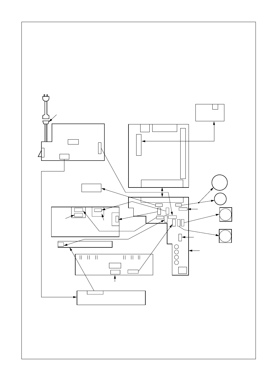
Appendix 4. Connection Diagram, HL-1050
A - 4
RS-100M
SERIAL I/F
P1 CDCC I/F
SLIOT SIMM
MAIN PCB
P2 ENGINE I/F
MAIN
MOTOR
SUB
MOTOR
FAN1
FAN2
REGISTRATION
SENSOR
COVER SW
PANEL SENSOR
PCB
SW1
P1 ENGINE
P3
P9
PH2
P8
P4
SCANNER UNIT
P1
PH1
CN1
SCANNER
MOTOR
ERASE LAMP
P1
SR.B T/R DRM.B
VCLM
GRID
DEV
HVPS
PC141
CN1
PAPER SENSOR
THERMISTOR
HEATER
SOLENOID
CN1
LVPS
POWER
SW
INLET
AC INPUT
P3 OP I/O
CN101
LD PC8
P1
P6
P2
P5
P7
P10
P11
M
SW2
LEDs
TONER
SENSOR
P2
USB I/F
(80x80mm)
(60x60mm)
See also other documents in the category Brother Printers:
- HL-2240 (522 pages)
- HL-2240 (21 pages)
- HL-2240 (2 pages)
- HL-2240 (150 pages)
- HL 5370DW (172 pages)
- HL-2170W (138 pages)
- HL 5370DW (203 pages)
- HL 2270DW (35 pages)
- HL 2270DW (47 pages)
- HL 5370DW (55 pages)
- HL-2170W (52 pages)
- HL-2170W (137 pages)
- PT-1290 (1 page)
- DCP-383C (7 pages)
- DCP-385C (122 pages)
- MFC 6890CDW (256 pages)
- DCP-585CW (132 pages)
- DCP-385C (2 pages)
- Pocket Jet6 PJ-622 (48 pages)
- Pocket Jet6 PJ-622 (32 pages)
- Pocket Jet6 PJ-622 (11 pages)
- Pocket Jet6Plus PJ-623 (76 pages)
- PT-2700 (90 pages)
- PT-2700 (180 pages)
- PT-2100 (58 pages)
- PT-2700 (34 pages)
- PT-2700 (62 pages)
- HL 5450DN (168 pages)
- HL 5450DN (2 pages)
- HL 5450DN (2 pages)
- DCP-8110DN (22 pages)
- HL 5470DW (30 pages)
- MFC-J835DW (13 pages)
- DCP-8110DN (36 pages)
- HL 5470DW (177 pages)
- HL 5450DN (120 pages)
- DCP-8110DN (13 pages)
- HL 5470DW (34 pages)
- HL-S7000DN (9 pages)
- HL-6050D (179 pages)
- HL-6050D (37 pages)
- HL-7050N (17 pages)
- HL-6050DN (138 pages)
- PT-1280 (1 page)
- PT-9800PCN (104 pages)