Caution – Burnham ALP150 User Manual
Page 26
26
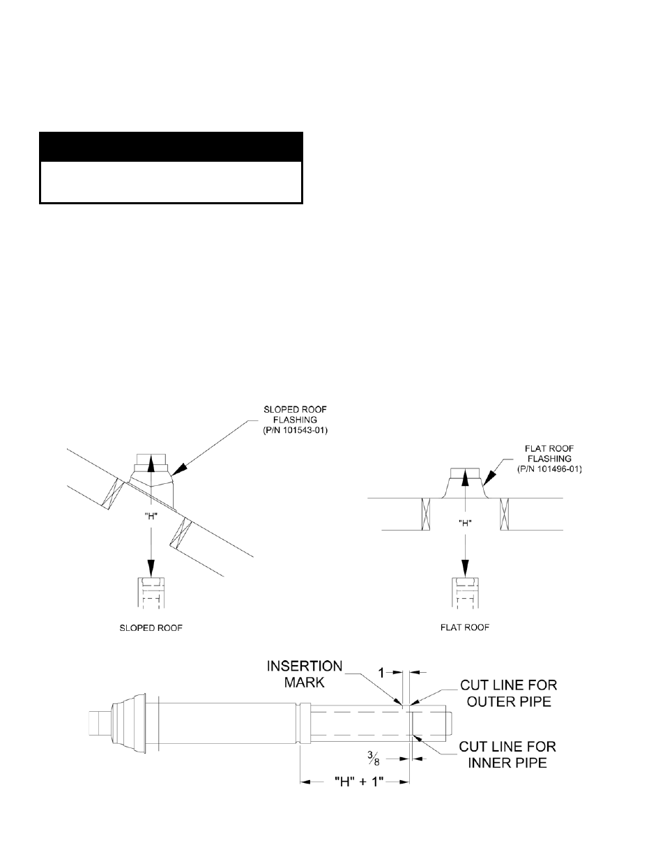
Figure 26: Cutting Vertical Terminal
a. Determine the centerline of the terminal location
on the roof. For flat roof, cut either 5-1/2”
diameter hole (80/125 mm concentric vent size)
or 6-1/2” diameter hole (100/150 mm concentric
vent size) for the terminal. For sloped roof, cut a
hole in the roof large enough for the terminal to
pass through the roof while remaining plumb.
CaUTiOn
if the boiler is located directly under the hole,
cover it while cutting the hole to prevent debris
from falling onto boiler.
b. Install the roof flashing using standard practice
on the roofing system of the structure.
c. If not already done, assemble the venting system
inside the building. The last section of pipe needs
to be on the same center line as the terminal
and within 19-1/4” of the top edge of the roof
flashing.
d. Measure distance “H” from the top edge of the
storm collar to the end of the last fitting as shown
in Figure 25.
e. Add 1” to distance “H”. Carefully mark this
length on the pipe as shown in Figure 26.
f. Cut the
outer pipe only at the point marked in
Step (e) using aviation shears, a hacksaw, or an
abrasive wheel cutter. Be careful to cut the pipe
square. De-burr the cut end with a file or emery
cloth.
g. Place a mark on the plastic inner pipe 3/8”
beyond the end of the outer pipe (Figure 26).
Use a fine tooth hacksaw to cut the plastic pipe
and be careful to cut the pipe square. De-burr the
cut edge of the plastic pipe with a file or emery
cloth.
h. Make a mark on the terminal section 1” from the
cut end of the outer pipe as shown in Figure 26.
i. Slip the terminal section through the roof from
the outside. Push into the last section of vent
pipe until the mark made in Step (h) is not
longer visible. Secure the terminal to the last
piece of pipe with three #10 x 1/2” sheet metal
screws. Drill a 1/8” hole through both outer
pipes to start these screws. Use a drill stop or
other means to ensure that the drill bit does
not penetrate more than 3/8” into the outer
pipe. Do not use a sheet metal screw longer
than 1/2”.
j. Secure the terminal section to the inside of
the roof structure using the mounting bracket
provided with the terminal (Figure 27).
Figure 25: Dimension "H"