Notice – Burnham ALP150 User Manual
Page 16
16
7. Install Rodent Screen and Combustion Air Terminal
(supplied with boiler), see Figure 8 for appropriate
configuration.
8. Apply sealant between vent pipe and opening to
provide weather-tight seal
F.
CPVC/PVC Vertical Venting System
Refer to Figures 3, 4, 5, 8, 9 & 10.
nOTiCE
Roof penetrations require the use of roof flashing
and storm collar that are not supplied with boiler.
Vent Piping - Vertical
1. See Paragraph D for instructions on attaching the
vent system connector to the boiler.
2. Do not exceed maximum vent length. Refer to
Table 7 for pipe diameters and allowable lengths.
3. Horizontal vent pipe must maintain a minimum ¼
inch per foot slope down towards boiler.
4. Install fire stops where vent passes through floors,
ceilings or framed walls. The fire stop must close
the opening between the vent pipe and the structure.
5. Whenever possible, install vent straight through the
roof. Refer to Figures 9 and 10.
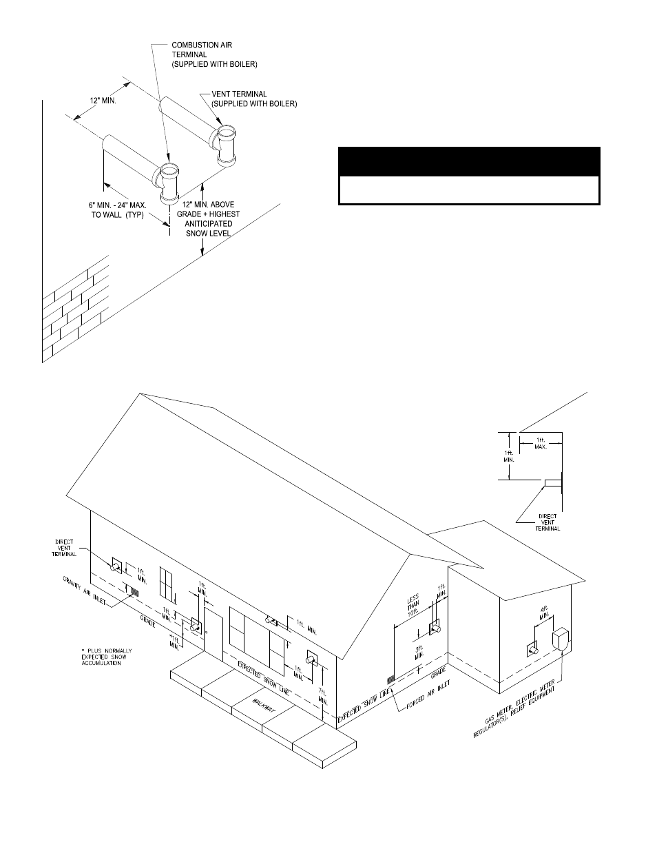
Figure 6 : Direct Vent - Side Wall Terminations
Figure : Location of Vent Terminal Relative to Windows, Doors, grades,
Overhangs, Meters and Forced air inlets (Combustion air Terminal not shown)