Burnham ALP150 User Manual
Page 19
19
5. Install maximum vertical run of seven (7) feet of
Schedule 40 PVC vent pipe. See Figure 11.
6. At top of vent pipe length install another PVC 90°
elbow so that elbow leg is opposite the building’s
exterior surface.
7. Install Rodent Screen and Combustion Air Terminal
(supplied with boiler), see Figure 8 for appropriate
configuration.
8. Brace exterior piping if required.
H.
The following information is applicable for
Combination Concentric Gas Vent/Combustion air
System (optional).
I.
Field Installation of Boiler Concentric Vent Collar
The Boiler Concentric Vent Collar is shipped inside the
boiler in plastic bag. The Collar mounting hardware
- six (6) #8 x ½” black oxide round head Phillips sheet
metal screws - are shipped inside Miscellaneous Part
Carton.
1. Release four side draw latches and remove boiler
lower front door assembly to gain access to the Vent
Collar.
2. Remove the collar from the bag and set aside.
3. Locate and remove six mounting screws.
4. Position the Collar onto jacket combination rear/
bottom panel and insert collar inner stainless steel
vent pipe into the heat exchanger vent outlet.
5. Align collar plate clearance holes with rear/bottom
panel engagement holes; then secure the collar to
rear/bottom panel with six mounting screws. See
Figure 12.
6. Flue temperature sensor, factory attached to the
boiler wiring harness, is secured to the boiler rear/
bottom panel with tape.
7. Remove the tape and push the sensor rubber plug
into Concentric Vent Collar sensor port until the
plug is securely engaged. See Figure 12.
The installation of the Concentric Vent Collar is now
completed.
J.
General Guidelines - Concentric Venting
1. Vent system installation must be in accordance
with National Fuel Gas Code, NFPA 54/ANSI
Z221.3 or applicable provisions of local building
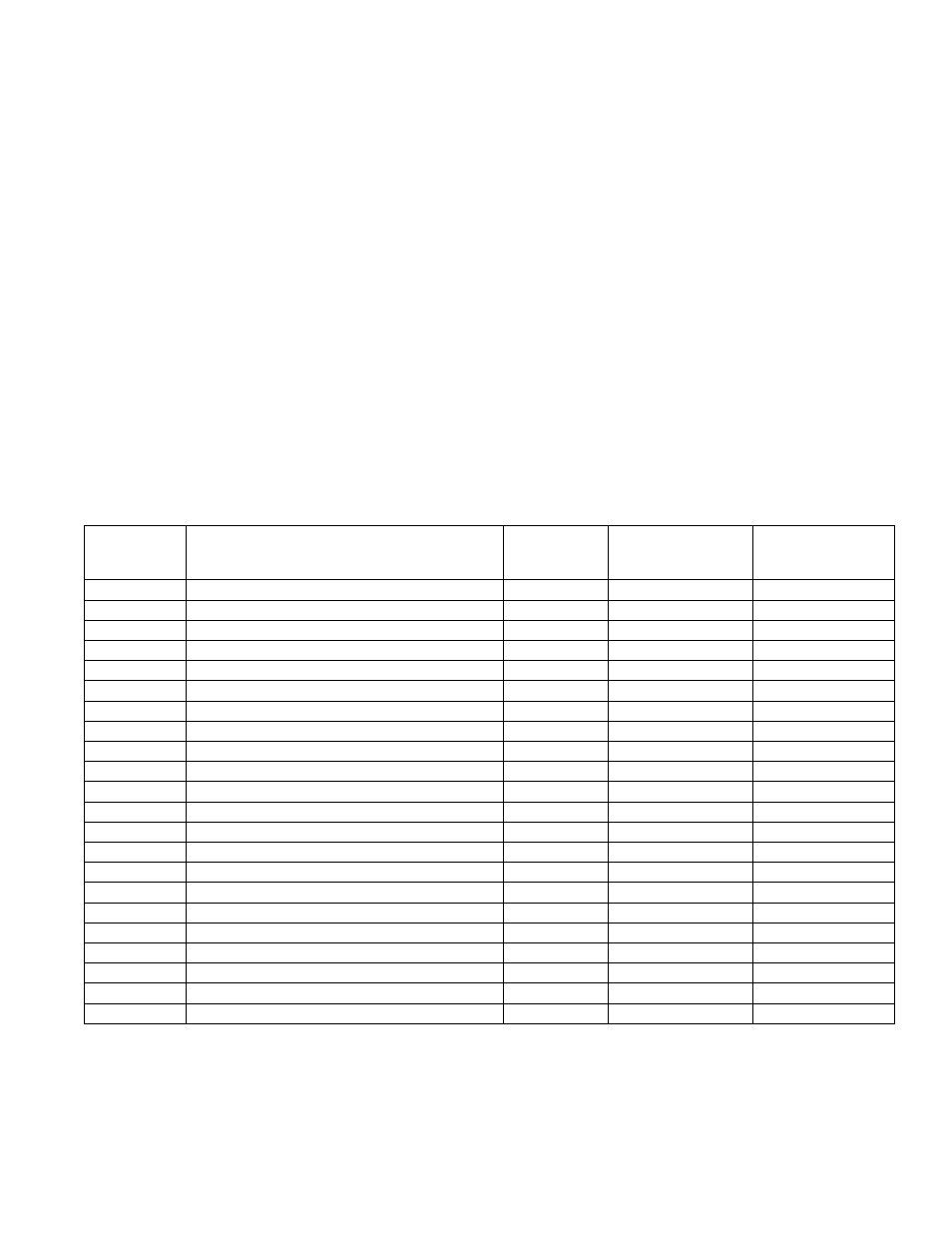
Table 8: Concentric Vent Components
Part Number
Component Description
Size
Component
Equivalent Vent
Length, Ft
Comments
101493-01
90° Elbow – Long Radius
80/125 mm
5.5
101491-01
45° Elbow - Long Radius
80/125 mm
3.0
101163-01
Cut -To-Length Extension, 500 mm (19-1/2”)
80/125 mm
1.63
**Can be cut
101162-01
Cut -To-Length Extension, 1000 mm (39”)
80/125 mm
3.25
**Can be cut
101485-01
Fixed Extension, 2000 mm (78”)
80/125 mm
3.25
***Must not be cut
101808-01
Horizontal (Wall) Terminal
80/125 mm
*NA
Supplied with boiler
101495-01
Vertical Roof Terminal
80/125 mm
*NA
See Note 1
101496-01
Flat Roof Flashing
80/125 mm
101497-01
Sloped Roof Flashing
80/125 mm
See Note 2
101492-01
Support Elbow with Chimney Chase Bracket
80/125 mm
8.5
See Note 3
101498-01
Hanger Wall Bracket
80/125 mm
101548-01
90° Elbow – Long Radius
100/150 mm
8.0
101549-01
45° Elbow - Long Radius
100/150 mm
3.0
101550-01
1 Cut -To-Length Extension, 500 mm (19-1/2”)
100/150 mm
1.63
** Can be cut
101551-01
Cut -To-Length Extension, 1000 mm (39”)
100/150 mm
3.25
** Can be cut
101553-01
Fixed Extension, 2000 mm (78”)
100/150 mm
6.5
*** Must not be cut
101809-01
Horizontal (Wall) Terminal
100/150 mm
* NA
Supplied with boiler
101557-01
Vertical (Roof) Terminal
100/150 mm
* NA
See Note 1
101558-01
Flat Roof Flashing
100/150 mm
101559-01
Sloped Roof Flashing
100/150 mm
See Note 2
101560-01
Support Elbow with Chimney Chase Bracket
100/150 mm
10.0
See Note 3
101561-01
Hanger Wall Bracket
100/150 mm
notes:
*
NA – do not include vent terminal into total vent length calculations.
**
These sections have plain male end and beaded female end. See Figure 11 for details.
***
These sections have beaded male end and beaded female end. See Figure 12 for details.
1. Vertical terminal can be used with either of the roof flashings listed beneath it.
2. Sloped roof flashing suitable for roof angles between 25° and 45°.
3. Used at base of vertical run inside unused masonry chimney.