Removing and replacing the silkworm 4016 – Brocade Communications Systems SILKWORM 4016 User Manual
Page 41
SilkWorm 4016 Hardware Reference Manual
4-7
Publication Number: 53-1000175-01
Removing and Replacing the SilkWorm 4016
4
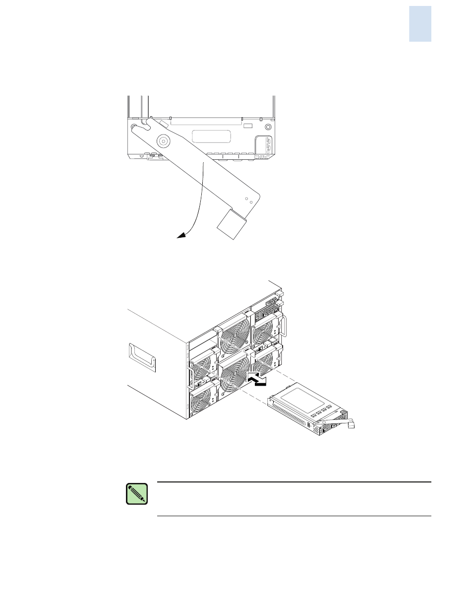
6.
Gently pull the handle of the SilkWorm 4016 insertion arm out and toward you to release the
switch.
.
7.
Slide the switch out of the chassis I/O bay. In the following illustration the SilkWorm 4016 is
inserted in a horizontal oprientation. Other blade server chassis may require a vertical orientation.
8.
Within one minute, install a replacement switch or a filler module into the empty slot.
The replacement procedure is described in detail in
“Inserting a SilkWorm 4016 into the Chassis”
.
84-0000123-01 Rev. X
||||| |||| |||||||| |||||||| |||||||| ||||
RP040000111
scale: 1/8" = 1"
NET
1
NET
3
PSU
1
PSU
1
IO
IO
I
10
11
12
13
!
11
12
13
FA
N
mod
ule
mu
st
be
rep
laced
wi
thin
2 m
inu
tes
!
FA
N
mo
du
le
mu
st
be
rep
lace
d w
ithi
n 2
mi
nu
tes
!
IOIO
I
NET
2
NET
4
PSU
4
PSU
2
10
11
12
13
!
A
Note
If you are not replacing the switch, use a filler module to fill the empty slot to ensure
proper air flow. Do not leave the slot empty for longer than one minute.