Interpreting led activity – Brocade Communications Systems SILKWORM 4016 User Manual
Page 38
4-4
SilkWorm 4016 Hardware Reference Manual
Publication Number: 53-1000175-01
Interpreting LED Activity
4
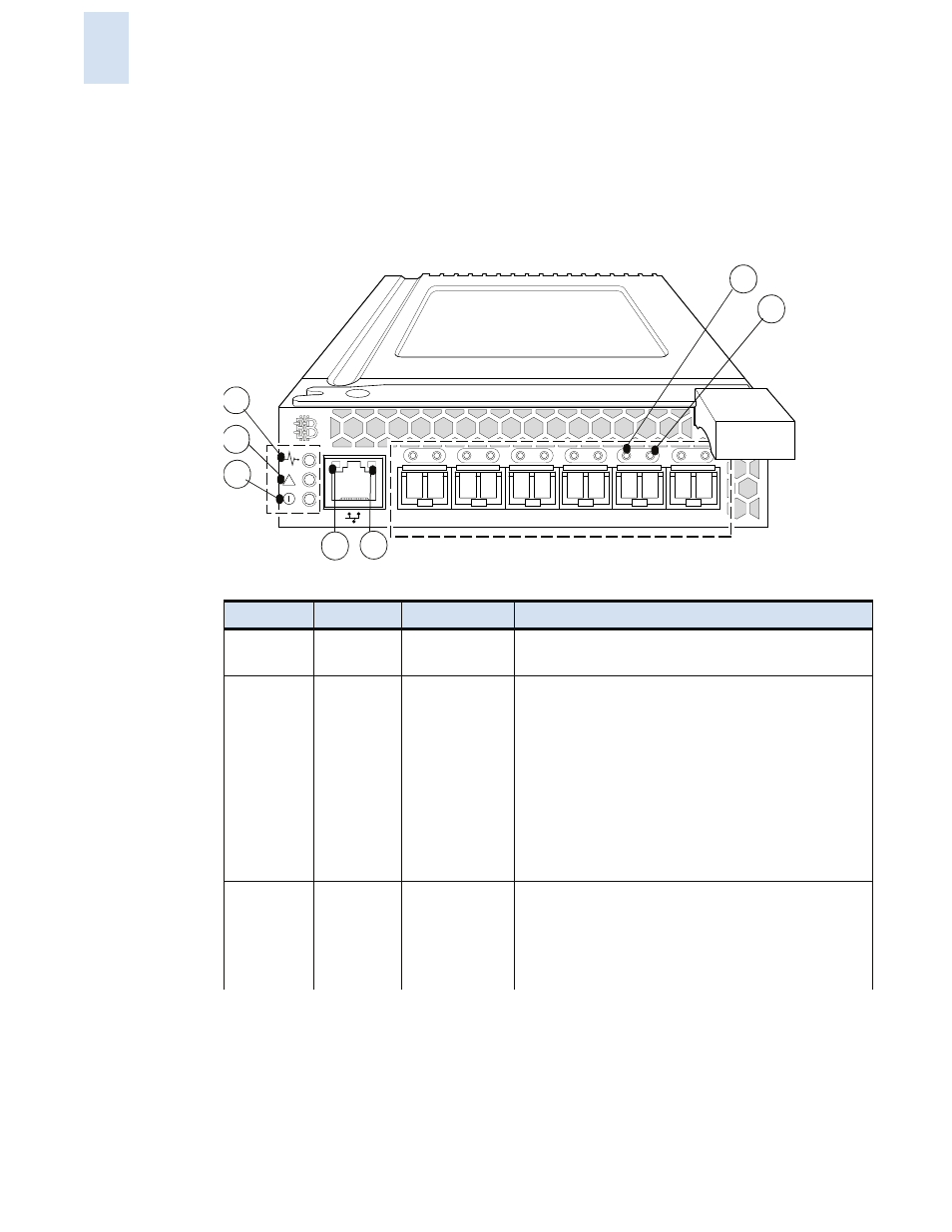
Interpreting LED Activity
Each SilkWorm 4016 uses LEDs to indicate status. These LEDs are shown in
. Not shown are
the two LEDs adjacent to each SFP, with one LED to indicate port speed and one LED to indicate
activity.
Figure 4-1
LED Locations
Location
Indicator
Color
Operation
1 blade
server
chassis
green/amber
Controlled by the blade server. Refer to the blade
serverdocumentation for details.
2
status
green/amber
•
Off: Switch is off or both power supplies from the
PowerEdge 1855) or onboard DCC have failed
•
Green: No errors and all ports are ready for use
•
Amber: Boot-up state, port(s) offline, or in reset
state
•
Blinking (2 Hz green/amber): One or more
environmental ranges are exceeded, or error log
contains diagnostic error messages
Note: The LED might blink during testing.
3
power green
•
Off: Switch is off or both power supplies (on the
PowerEdge 1855) or onboard DCC have failed
•
Green: Normal operation and power supply is
functioning properly. Power is supplied by the
blade server chassis
10
11
12
13
14
15
!
1
2
3
4
5
6
7