Port side, 1port side – Brocade Communications Systems SILKWORM 4016 User Manual
Page 18
1-4
SilkWorm 4016 Hardware Reference Manual
Publication Number: 53-1000175-01
Switch Characteristics
1
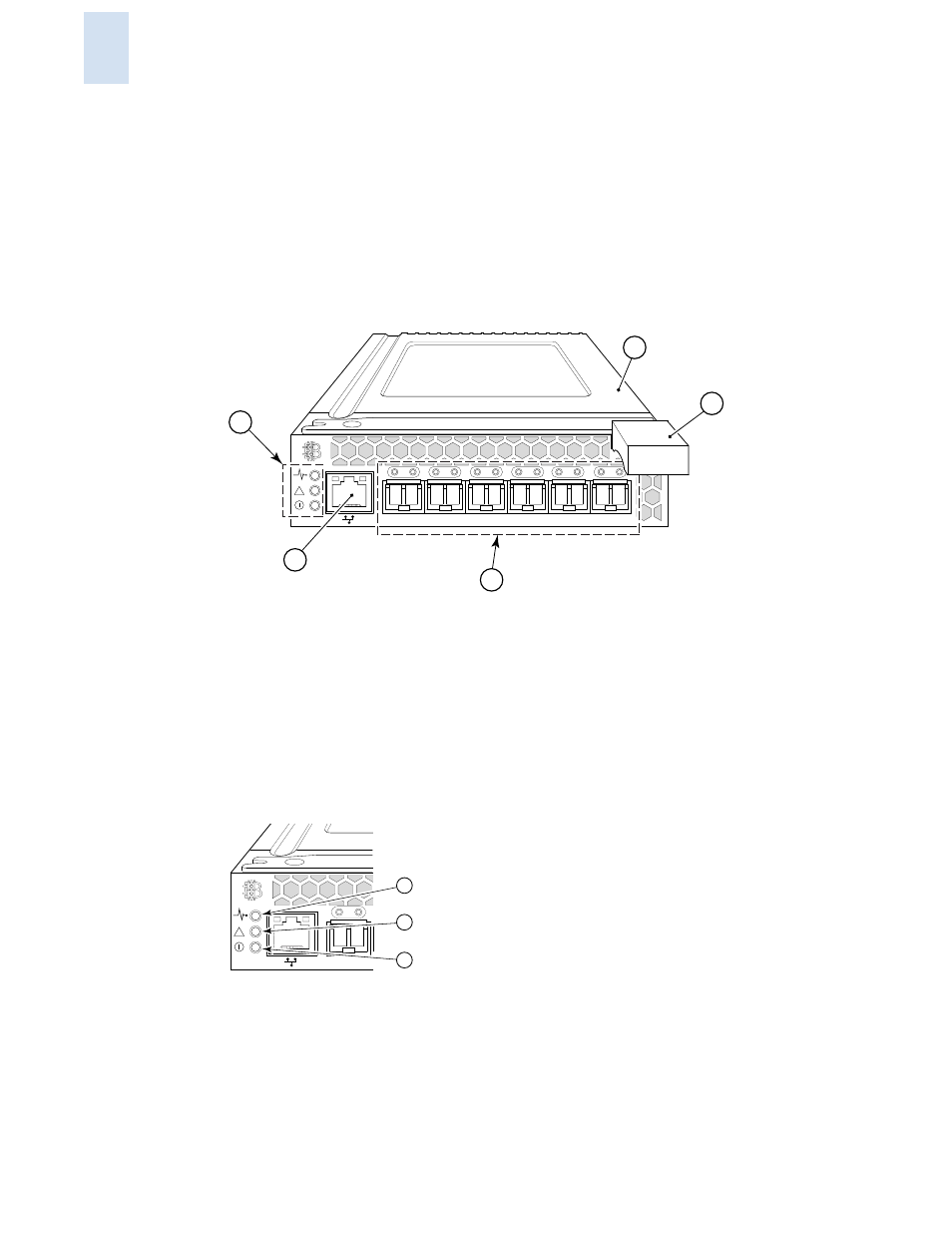
Port Side
Externally accessible ports and LEDs are on the port side of the switch. The port side faces out when the
switch is inserted into a .
details the switch’s port side. For a complete description of the
locations and interpretations of these LEDs, see
The insertion arm is located just above the port side of the SilkWorm 4016 and ends with a plastic
handle, accessible at the front of the port side of the switch. This arm is used to remove and insert the
unit as described in
“Inserting a SilkWorm 4016 into the Chassis”
Figure 1-1
Port Side of the SilkWorm 4016
1
Ethernet port
2
Power and status LEDs
3
Top of SilkWorm 4016
4
Insertion arm latch
5
Autosensing ports
The nonport (switch status) LEDs, shown as item 2 of
, display switch-level information as
.
Figure 1-2
Nonport LEDs
1
Module controller status
2
Switch status
3
Power and module status
10
11
12
13
14
15
!
3
5
1
2
4
10
!
1
2
3