4 waveform check, 5 check items – Anritsu MP1763C User Manual
Page 69
6-3
6.5 Check Items
Check the 1/8 SPEED output with the connection shown at the below.
Pattern
LOGIC
POS
PRBS
2
31
-1
Mark ratio
1/2
Check all the outputs with the connections DATA1
→ DATA2 → - - - → DATA8.
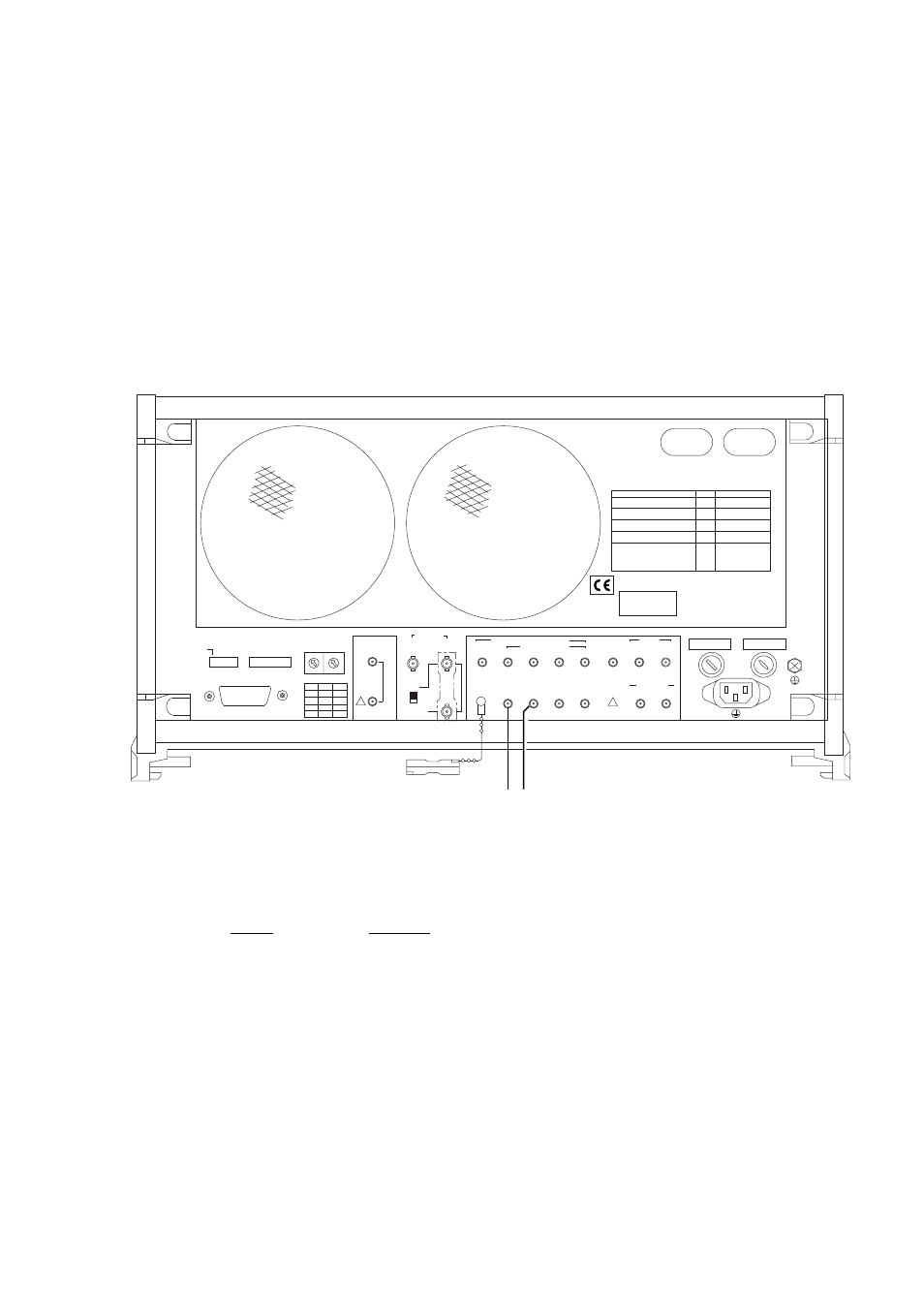
Fig. 6.3-2 Connection of rear panel
6.4 Waveform Check
Connect the MP1763C and sampling oscilloscope in accordance with 6.2-(2).
Check the DATA, DATA, CLOCK, and CLOCK1 waveforms.
Pattern
LOGIC
POS
PRBS
2
31
-1
Mark ratio
1/2
Output
DATA
amplitude
2.0 Vp-p
(CLOCK)
offset
0 V
OH
6.5 Check Items
Use a sampling oscilloscope to check that the amplitude, offset, raise, fall time, duty (CLOCK), and jitter (DATA) are
within the specifications.
* When measuring the jitter, use the divided 1/1CLOCK as the sync trigger.
!
!
Nameplate
LINE INPUT
47.5 - 63Hz 700VA MAX
1/8 SPEED ( ECL to - 2V )
ERROR
CLOCK
DATA OUTPUT
GATING DISABLE INJECTION
OUTPUT
1
2 3 4
INPUT INPUT INPUT
50
50
50
50
50
0/-1V 50
0/-1V 50
ALTERNATE
A/B TIMING
5
6
7
8
INPUT OUTPUT
50
50
50
50
ECL 50
STD 10MHz
BUFFER INPUT
OUTPUT TTL
EXT
INT
INTERNAL
SYNTHESIZER
OUTPUT
50
CLOCK
INPUT
50
ERROR
ADDITION CH
( 1 - 32 )
10
1
FUNCTION
GPIB
ADDRESS
SYSTEM
CONTROL 5 4 3 2 1 8 7 6 5 4 3 2 1
ON
OFF
1
0
1
0
GPIB
S111 A111 T 6
L 4 S R 1 R L 1
P P 0 D C 1 D T 1
C 1 C 2 C 3
C 4
WARNING
CAUTION
C 7
FUNCTION
ITEMS
SW
SPECIFICATION
0 : 1 BIT
1 : 3 BIT
SW6
SW5
0
0 :
0BIT
0
1 :
1BIT
1
0 :
2BIT
1
1 :
3BIT
2
3
4
5, 6
1
AND BIT SHIFT COUNT
FOR THE MARK RATIO
EXTERNA ERROR INJECTION
FLOPPY DISK FORMAT TYPE
ALTERNATE PATTERN
A/B SWITCHING TIMING
BIT SHIFT NUMBER FOR
ALTERNATE A/B SELECT TIMING
0 : 1440kB/720kB
1 : 1232kB/640kB
0 : INTERNAL
1 : EXTERNAL
0 : OFF
1 : ON