Section 5 principles of operation, 1 pseudorandom pattern (prbs pattern) – Anritsu MP1763C User Manual
Page 63
5-1
SECTION 5
PRINCIPLES OF OPERATION
5.1 Pseudorandom Pattern (PRBS Pattern)
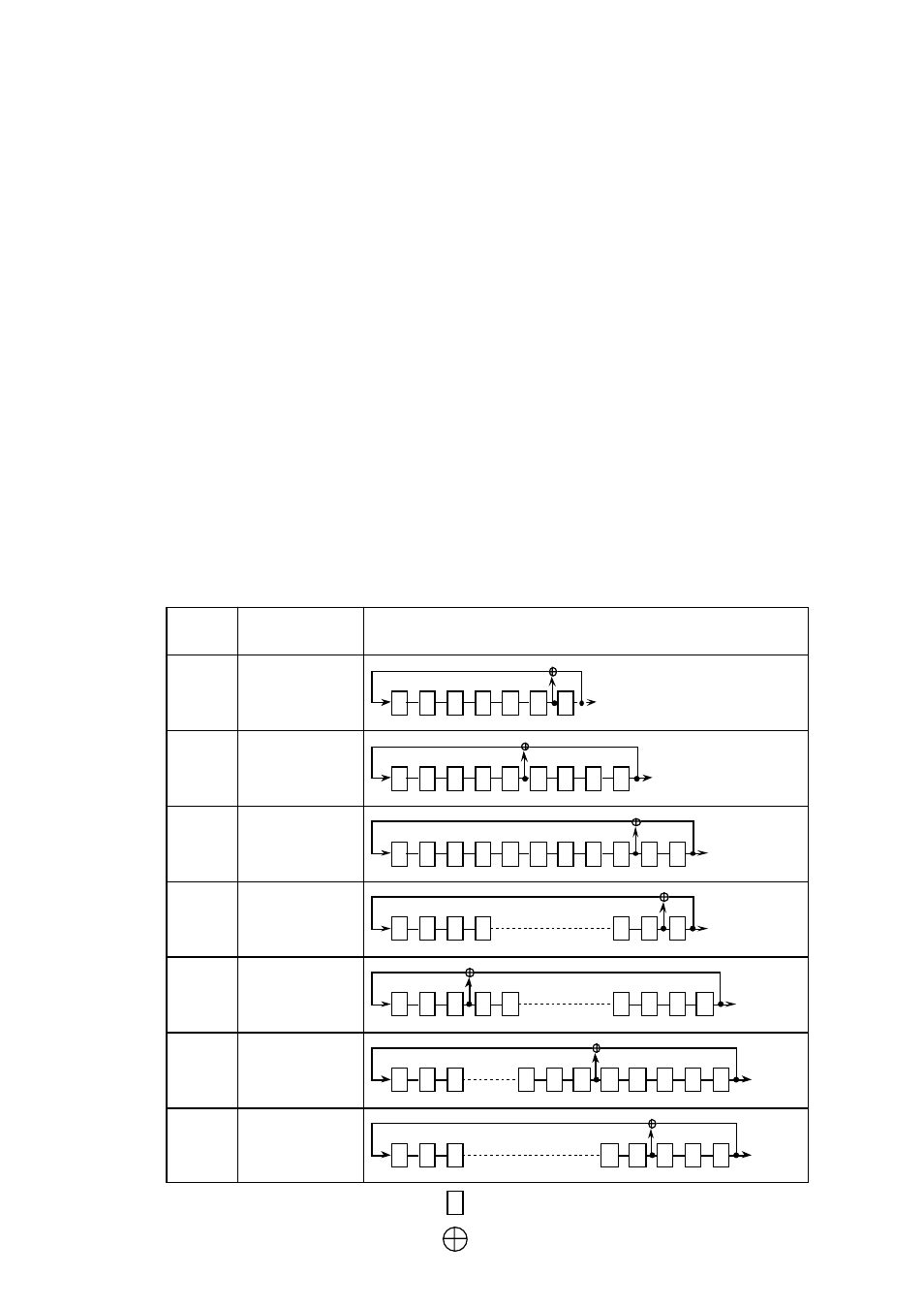
The principle of pseudorandom pattern generation is shown in Table 5.1-1. The pseudorandom pattern is represented by
the Nth-order generation polynomial shown in Table 5.1-1. One period is 2
N
-1. A PRBS pattern with a 2
N
-1 period
produces one N bits continuous “1” pattern per period.
When LOGIC is set to POS (positive logic), PRBS pattern output level “1” corresponds to low level and “0” corresponds
to High level.
The PRBS pattern mark ratio is generated by the block shown in Fig. 5.1-1. There are four mark ratios of 1/2, 1/4, 1/8, and
0/8 (all 0). For 1/4 and 1/8, 1-bit shift or 3 bit shift can be selected using the Dip switch on the rear of the instrument,
depending on the generation method (see section 4.6, “Functions of the FUNCTION Switch”).
When the rear panel 1/8 SPEED output is a PRBS pattern, a pattern is produced train as shown in Fig. 5.1-2.
Table 5.1-1 Principle of Pseudorandom Pattern Generation
Period
Generation
polynomial
Pattern generation block diagram
1
2
3
4
5
6
7
Output
1
2
3
4
5
6
7
Output
8
9
1
2
3
4
5
6
7
Output
8
9
10
11
1
2
3
4
Output
13
14
15
5
1
2
3
4
Output
17
18
20
19
16
1
2
3
Output
19
20
22
21
18
17
23
1
2
3
Output
27
28
30
29
31
N
: Shift register
: Exclusive-OR