2 specifications – Anritsu MP1763C User Manual
Page 18
1-2
Section 1 GENERAL
1.2 Specifications
Operation
frequency range
Internal Clock (OPTION 01)
0.05 to 12.5 GHz
Pattern
generation
PRBS
Continuous 0 pattern can be inserted up to pattern length -1.
Patterns
2 , 2 , 2
DATA
2
8388608 bits
2
65536
:
Step
1 bit
65536
131072
:
Step
2 bits
131072
262144
:
Step
4 bits
262144
524288
:
Step
8 bits
524288
1048576
:
Step
16 bits
1048576
2097152
:
Step
32 bits
2097152
4194304
:
Step
64 bits
4194304
8388608
:
Step
128 bits
Number of patterns A and B to be output can be specified.
Patterns A and B must be the same length.
Output control
Internal/external switchable
A/B switching
A/B each 1 to 127 times/step 1
128
4194304 bits/step 128 bits
Edit function
All 0 / All 1 / page 0 / page 1
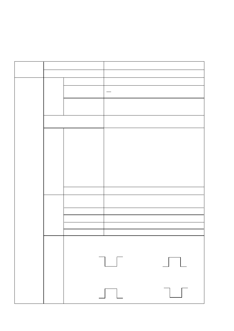
Logic
inversion
Positive / Negative switching possible
[PRBS]
Positive
Negative
H
“ 0 ”
H
“ 1 ”
L
“ 1 ”
L
“ 0 ”
[PRGM]
Positive
Negative
H
“ 1”
H
“ 0 ”
L
“ 0 ”
L
“ 1 ”
0.05 to 12.5 GHz
External Clock
2 -1 (N=7,9,11,15,20,23,31)
N
Pattern length
Mark ratio
1/2,1/4,1/8,0/8
(1/2,3/4,7/8,8/8 also possible by logic inversion)
Number of “AND
bit” shifts when setting
mark ratio
1 bit or 3 bits
(Selectable using rear panel DIP switch)
DATA length
Edit function
All 0 / All 1 / Page 0 / Page 1
Alternate
pattern
DATA length
Zero substitution
7 9 11 15
to
to
to
to
to
to
to
to