Anritsu MP1763C User Manual
Page 46
4-12
Section 4 OPERATING INSTRUCTIONS
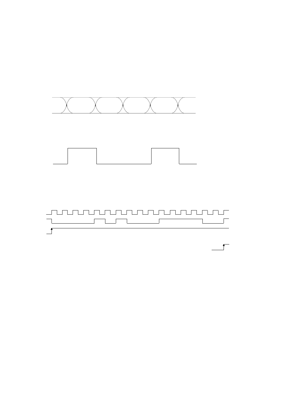
When the PRBS DATA output is monitored on a sampling oscilloscope using each synchronization output, the following
waveforms are shown:
1) 1/64 CLOCK
Shown as an eye pattern.
2) FIXED POSN
Shown as a 0 and 1 waveform.
and VAR POSN
At VAR POSN, the synchronization position shifts +16 (or -16) bits each time the PAGE/PATTERN SYNC POSITION
value is incremented (or decremented) by 1.
• The above figure is an example. Trigger output at the shown position is not specified.
• At FIXED POSN, the position is fixed to 1 of VAR POSN.