6 radar junction box connections, Terminal strip a – Seiwa SWRx series User Manual
Page 9
11
User Manual
reach the desired location for the On/Off control switch. If the leads
must go in different directions, first route the five leads in the fabric
braid to the Junction Box. Then extend the shorter leads using the
same size or larger size wire.
1.6
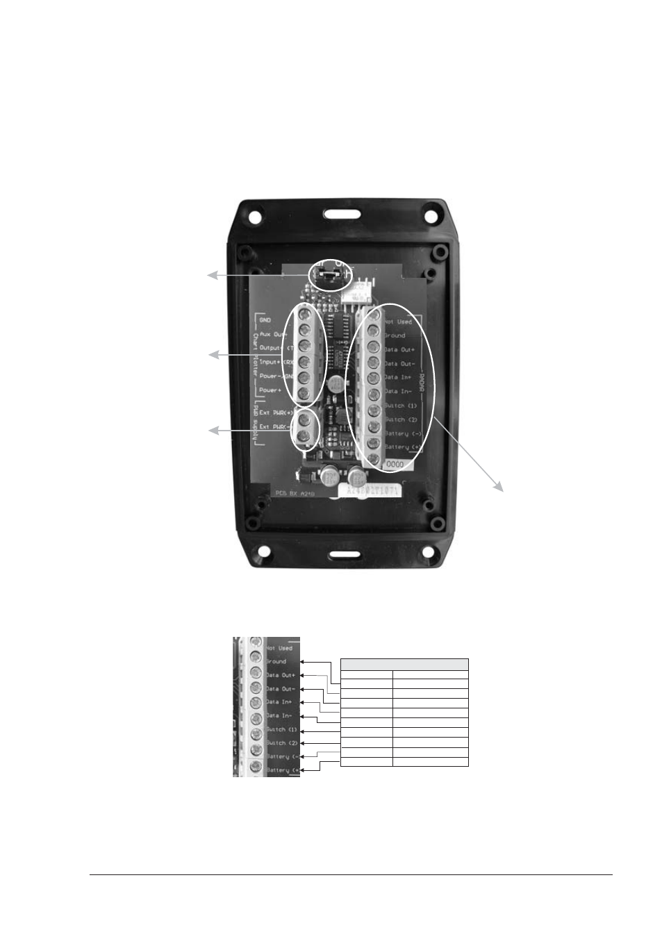
RADAR JUNCTION BOX CONNECTIONS
Referring to the diagram below, connect the color coded wires from the Radar
cable to the designated place on Terminal strip A in Radar Junction Box as follows.
MOUNTING
INSTRUCTIONS
1. Open the box unscrewing
the 4 bottom screws
2. Connect the Radar cable
to the terminal A
3. Connect the Power supply
to the terminal B
4. Connect the chart plotter
cable to the terminal C
5. Set up the jumper for
RADAR ON/OFF switch:
5a. Mount to permanently
power ON the Radar;
5b. Connect to a switch to
manually power on/off
the Radar;
5c. Remove to control the
power ON/OFF via
the chart plotter with
the external alarm
output signal.
Terminal C
CHART PLOTTER
(see connection tables)
Terminal B
POWER SUPPLY
(see Radar specifications)
JUMPER for RADAR
ON/OFF SWITCH
Terminal A
RADAR
(see Radar cable label)
Fig. 1.6 - Junction Box
Terminal Strip A
WIRE COLOR FUNCTION
DATA GND
DATA OUT+
DATA OUT-
DATA IN+
DATA IN-
POWER ON/OFF SWITCH 1
POWER ON/OFF SWITCH 2
RADAR SUPPLY-
RADAR SUPPLY+
BLACK
ORANGE
YELLOW
BROWN
RED
GREEN
BLUE
BLACK (large wire)
WHITE (large wire)
RADAR CABLE
Fig. 1.6a - Terminal Strip A Connection for SWR 1/SWR 8/SWR 9