B. installation, B.1 more installation considerations, B.2 installing scanner unit – Seiwa SWRx series User Manual
Page 51
53
User Manual
B. Installation
B.1
MORE INSTALLATION CONSIDERATIONS
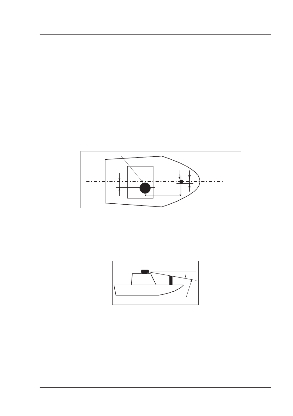
B.1.1 Shifting from keel line
By shifting the scanner position from the keel line to the starboard side of the
boat, it is possible to move shadow zones to the port side. This makes it possible
to keep a clear view to the bow. The distance to be shifted can calculated using
the following equation:
Ls = 0.4R+D/2 [m] (when R<15m)
Ls = 0.025R+D/2 [m] (when R>=15m)
where Ls = distance to be shifted from keel line
D = diameter of obstacle on keel line
R = distance from scanner to obstacle
Ls
R
D
Scanner Unit
Obstacle
Keel
Fig. B.1.1 - Shifting from keel line
B.1.2 Obtaining sufficient dip angle
Raise the scanner position so that there is a sufficient dip angle available between
the line of sight from the scanner to the obstacle and the horizontal line. By
raising the dip angle above 5°, it is possible to prevent mid- and long-distance
shadow zones. The Radar cannot detect objects below the line of sight.
Horizontal line
Line of sight
θ
Fig. B.1.2 - Obtaining sufficient dip angle
B.2
INSTALLING SCANNER UNIT
Use a mounting base such as the ones shown in Fig. B.1.1, or you can install the
scanner directly to a roof or other flat surface. Be certain you keep the water
drain tube clear. It’s located at the bottom of the scanner unit.