12 user manual, Terminal strip b, 24 vdc – Seiwa SWRx series User Manual
Page 10
12
User Manual
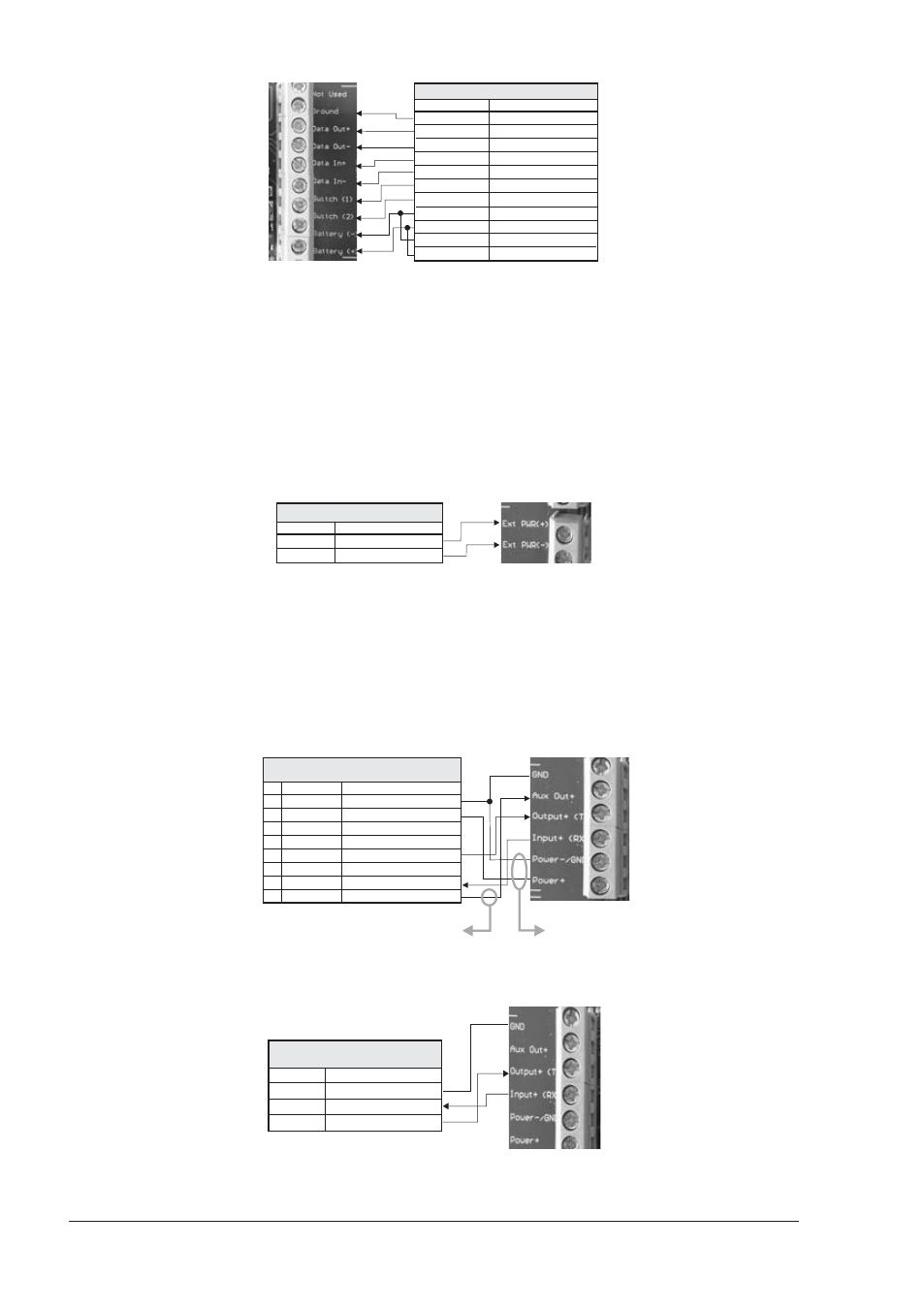
WIRE COLOR FUNCTION
DATA GND
DATA OUT+
DATA OUT-
DATA IN+
DATA IN-
POWER ON/OFF SWITCH 1
POWER ON/OFF SWITCH 2
RADAR SUPPLY-
RADAR SUPPLY+
MOTOR POWER-
MOTOR POWER+
BLACK
ORANGE
YELLOW
BROWN
RED
GREEN
BLUE
BLACK (large wire)
WHITE (large wire)
BLUE (large wire)
RED (large wire)
RADAR CABLE
Fig. 1.6a1 - Terminal Strip A Connection for SWR 10
Terminal Strip B
IS
TO
BE
CONNECTED
TO
POWER
SUPPLY
(12
TO
24 VDC
NOMINAL
)
Do not omit the in-line fuse unless a dedicated and fused terminal is available. If
so, install a 5 Amp fuse. If you are installing a SWR 10 open scanner Radar, it is
important to also connect the Red (+) to positive power terminal, and Blue (-) to
negative power terminal, as this provides power to scanner motor.
This terminal leads the power to the Scanner unit and to the chat plotter (*).
NOTE(*)Only if the chart plotter power wires are connected to Terminal strip C, on B+
and GND terminals.
WIRE COLOR FUNCTION
POWER SUPPLY+
POWER SUPPLY-
RED
BLACK
12-24V POWER SUPPLY
Fig. 1.6b - Terminal Strip B
WARNING
Please make sure that the connected power supply is able to supply the
current at the voltage required by the Radar to operate.
Terminal Strip C
See connection tables to determine proper way to connect the chart plotter to
Radar Junction Box.
PIN WIRE COLOR FUNCTION
GND/COMMON
POWER INPUT+ (10-35 Vdc)
INPUT 1+
INPUT 1-
OUTPUT 2+
OUTPUT 1+
INPUT 2+
+
OUTPUT EXTERNAL ALARM
1
2
3
4
5
6
7
8
BLACK
RED
WHITE
GREEN
GRAY
YELLOW
BROWN
BLUE
POWER & I/O CABLE
CONNECTION TO PORT 2
Connect to power the
chartplotter via the junction box
Connect to control the Radar ON/OFF via the chart plotter. Make sure that:
1) This signal is not used for any other operation (external alarm)
The jumper is removed on the junction box
2)
Fig. 1.6c - Connection to Port 2
WIRE COLOR FUNCTION
GND
INPUT 2+
OUTPUT 2+
BLACK
BROWN
GRAY
QUICK DISCONNECT
BRACKET CABLE
Fig. 1.6c1 - Connection to Port 2 for Quick Disconnect Bracket Cable