Lubricator overview, 4 setting lubricator drip rates, 5 filling methods – Norgren Lubricators User Manual
Page 3: 3 lubricator sizing
Lubricator Overview
Littleton, CO USA
Phone 303-794-2611
Fax 303-795-9487
ALE-14-C
1.4
SETTING LUBRICATOR
DRIP RATES
1.4.1
What is the Correct Drip Rate Setting?
The drip rate will depend on the application, the
amount of lubrication required, the flow through the
lubricator and the lubricator type. In Micro-
Fog
lubr
icators only 10% of the droplets in the sight
dome are carried downstream. The drip rate in
Micro-Fog lubricators therefore tends to be much
higher.
The following table can be used to estimate
drip rate for required flow. This is very much a rule
of thumb. In practice it is necessary to fine tune the
oil drip rate in each application.
Typical Drip Rate
Typical Drip Rate
Approx
per Minute
per Minute
Flow
Micro-Fog
Oil-Fog
scfm
(dm3/s)
20
2
10 (5)
40
4
20 (10)
60
6
30 (15)
80
8
40 (20)
100
10
50 (25)
120
12
60 (30)
1.3.2
Can the Drip Rate be Shut Off?
In lubricators with needle valve type sight dome,
yes.
Some Norgren sight domes use a felt pad
which is soaked in oil at the point where the drops
are formed. With this type of sight dome the oil
droplets cease once the felt pad dries out.
With the new style dome (L72/73/74 and
L07) complete shut off is not possible. Minimum
adjustment for the drip rate is around 1 drop per
minute.
1.5
FILLING METHODS
1.5.1
Oil-Fog and Micro-Fog Lubricators:
The standard Oil-Fog lubricators can be filled under
pressure ie without switching off the upstream air.
When a fill plug is removed a check valve in the
lubricator body isolates the inlet pressure from the
bowl and the reservoir will depressurize. The
lubricator can then be filled with oil. When the fill
plug is replaced, the reservoir will re-pressurize.
The standard Micro-Fog unit can only be
filled without isolating the upstream pressure if a
remote fill or quick fill nipple accessory is fitted. To
remove the fill plug of a Micro-Fog lubricator whilse
under pressure can be dangerous. If in doubt shut
off the upstream air!
1.5.2
Remote Fill Devices:
The remote oil fill system provides a means of filling
from a remote fill point, a single lubricator or a bank
of lubricators manifolded together. The remote fill
point may be connected to a portable reservoir or to
a centralized, permanent reservoir. A portable
reservoir permits the use of different lubricants in
different groups of lubricators to suit the
requirements of the machinery being lubricated. The
lubrication oil must be fed in at a higher pressure
than exists in the bowl.
The devices are NOT intended for
connection to an oil feed line which is under
constant pressure from a pump or pressurized
reservoir. The device cannot reset until the pressure
is removed. Such lines are a potential safety hazard
if they should leak or become broken.
1.5.3
Quick Fill Nipples:
The quick fill system is an alternative which allows
ease of filling a single Micro-Fog or Oil-Fog
lubricator without switching off the mains air (on
some units the quick fill nipple replaces the filler
plug).
To fill the lubricator, a quick fill connector
piped to a portable oil reservoir is snapped in place
over the quick fill nipple. The main oil reservoir can
now be pumped (or pressurized) to a pressure
greater than the lubricator bowl and the lubricator
filled.
1.3
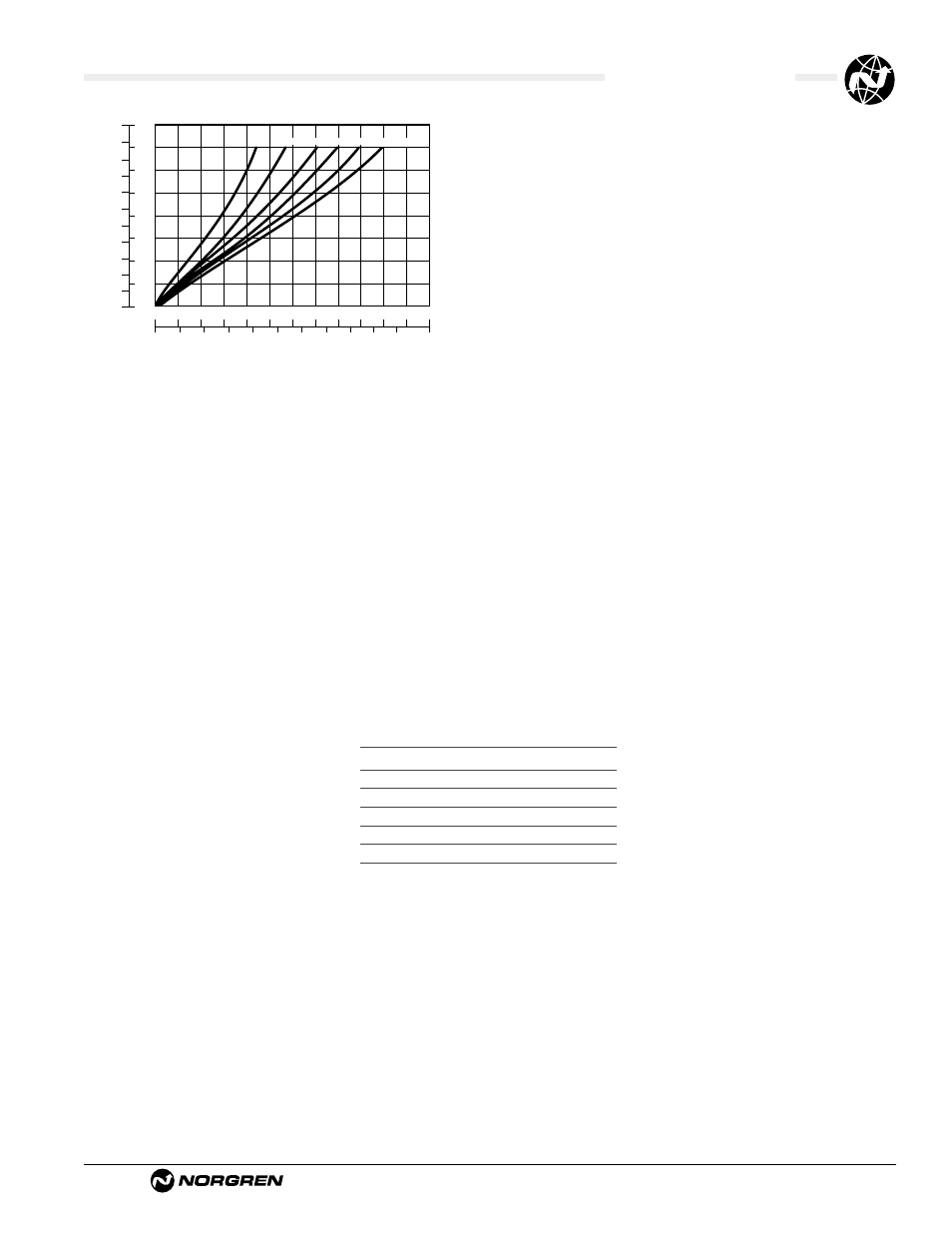
LUBRICATOR SIZING
Lubricators are sized by downstream flow
requirements. An analysis of air flow use must be
made. After determining how much air flow is
needed, a lubricator can be chosen. Manufacturers’
curves will be like the one shown. For example, 50
scfm of 90 psig lubricated air is required. Enter the
curve on the horizontal axis at the required flow.
Read up to intersect the 90 psig line. Read the
pressure drop on left, vertical axis as approximately
2.3 psid. Pressure drop should be less than 5 psid.
If pressure drop is more than 5 psid, choose a larger
lubricator.
Always be sure that the lubricants in your system are
compatible with the materials in the lubricator you
choose. This is especially important for plastic
lubricator reservoirs. If in doubt, check with the
factory or use a metal reservoir.
0
0
0
10
20
30
40
50
Air Flow
Flow Characteristics
60
70
80
90
100
20
40
60
80 100 120 140 160 180 200
scfm
dm 3/s
0
.1
.2
.3
.4
.5
bar
psig
1
2
3
4
5
6
7
Pressure Drop
35
60
90
120 160 180 psig