Air-oil tank volumes (cubic inches), Rod alignment coupler, Air-oil tank – Norgren NFPA Aluminum & Steel Cylinders User Manual
Page 94: How to figure length of volume, Air-oil tank dimensions, Rod alignment coupler dimensions, Act-1-94, Available in 5 practical bore sizes: 1
ACT-1-94
Brookville, OH USA
Phone 937-833-4033
www.norgren.com
Series A, NFPA Aluminum Air Cylinders (ø1-1/2" to 8"), Cylinder Features
All Dimensions in Inches (mm)
(38.10)
(68.25)
(101.60)
(142.88)
(219.08)
(31.75)
(50.80)
(63.50)
(63.50)
(76.20)
(19.05)
(101.60)
(127.00)
(127.00)
(168.28)
(19.05)
(120.65)
(152.40)
(152.40)
(203.20)
(9.53)
(12.70)
(12.70)
(17.45)
(3.18)
(4.75)
(4.75)
(6.35)
(63.50)
(95.25)
(139.70)
(215.90)
(44.45)
(69.85)
(107.95)
(180.98)
(11.10)
(14.27)
(14.27)
(20.62)
(3.18)
(9.53)
(12.70)
(12.70)
(19.05)
(3.18)
(6.35)
(9.53)
(9.53)
(12.70)
1.500
2.687
4.000
5.625
8.625
1.250
2.000
2.500
2.500
3.000
.750
4.000
5.000
5.000
6.625
.750
4.750
6.000
6.000
8.000
.375
.500
.500
.687
.125
.187
.187
.250
2.500
3.750
5.500
8.500
1.750
2.750
4.250
7.125
.437
.562
.562
.812
.125
.375
.500
.500
.750
.125
.250
.375
.375
.500
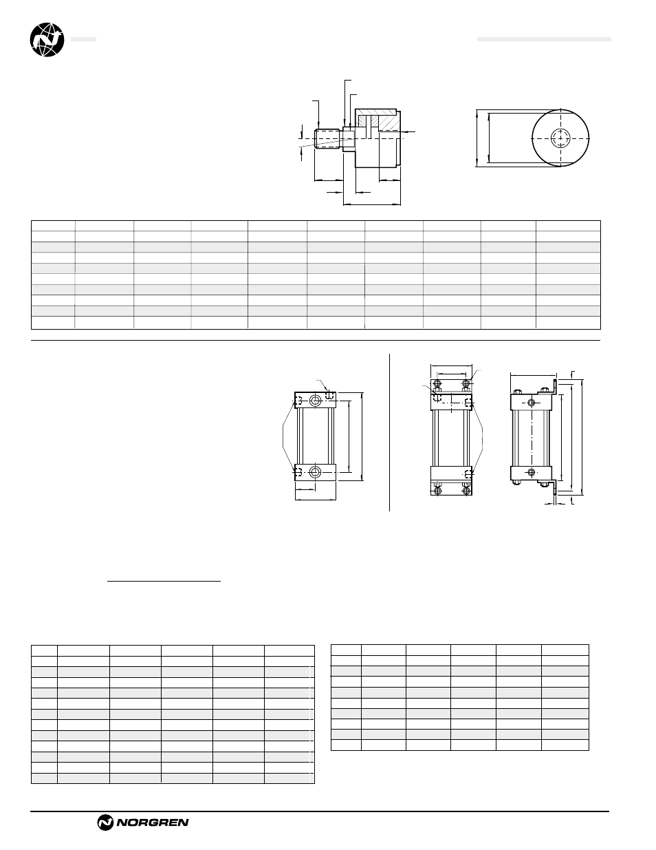
Air-Oil Tank Volumes (cubic inches)
G Across Flats
øF Shank
.062
Radial Float
2˚ Spherical
Motion
øB
A Thds.
A Thds.
E
E
D
C
H Across
Flats
Rod Alignment Coupler
The Rod Alignment Coupler allows 1/16" of radial
float and 2° of spherical movement. This prevents
cylinder binding due to misalignment thus
extending bearing and seal life, and permits
greater tolerance between the centerline of the
cylinder and mating part for simplified installation.
Air-Oil Tank
Available in 5 practical bore sizes: 1
1
/
8
", 2", 3
1
/
4
",
5", and 8", the Air-Oil Tank includes a translucent
fiberglass tube which permits viewing of the tank
oil level from any position, internal baffles that
reduce foaming and aeration of the system oil
resulting in maximum cylinder control, and
standard angle mounting brackets (except 1
1
/
8
"
bore) easily removed for convenient fluid
port positioning.
How to Figure Length of Volume
The following equations are given to help you in selecting the right air/oil tank volume for your particular application.
Volume of Cylinder: • Cap End
Cylinder Bore Area x Stroke = Volume
• Head End
Cylinder Bore Area – (Piston Rod Area*) x Stroke = Volume *
Reference Page ACT-1-13 for Areas.
Length of Tank = Volume of Cylinder x 1.3** (See chart below.)
**30% minimum recommended reserve working volume.
Tank Bore Area
Final Length of Volume of Tank = Working length of tank + 2" minimum safety factor to prevent aeration of oil.
Note: Length must be at least 3".
øJ (4)
L NPT
Fill Port
K NPT
Port
*C *B
D
A
K NPT
Port
G
H
L NPT
Fill
Port
F
E
*D
*C
*B
E
A
1 1/8" Bore only
*plus internal length
.995 sq."
3.14 sq."
8.30 sq."
19.64 sq."
50.26 sq."
5.9
18.6
49.8
117.8
301.5
7.9
25.1
66.4
157.1
402.0
9.9
31.4
83.0
196.4
502.6
11.9
37.6
99.6
235.6
603.1
13.9
43.9
116.2
274.9
703.6
15.9
50.2
132.8
314.2
804.1
17.9
56.5
149.4
353.5
904.5
19.9
62.8
166.0
392.8
1005.2
Bore
1-1/8"
2"
3-1/4"
5"
8"
Area
6"
8"
10"
12"
14"
16"
18"
20"
Internal Length of Tank
Air-Oil Tank Dimensions
How to Order: Specify air-oil tank part number and internal length.
Example: 2" bore with 6" internal length = AOT-04 x 6
Note: Maximum operating pressure 250 PSI.
Bore
1-1/8"
2"
3-1/4"
5"
8"
AOT-225
AOT-04
AOT-065
AOT-10
AOT-16
A
B
C
D
E
–
F
–
G
–
H
–
øJ
–
K
L
(31.75)
(31.75)
(31.75)
(44.45)
(44.45)
(63.50)
(63.50)
(82.50)
(82.50)
(50.80)
(50.80)
(50.80)
(58.72)
(58.72)
(74.60)
(74.60)
(111.13)
(111.13)
(12.70)
(12.70)
(12.70)
(12.70)
(12.70)
(12.70)
(12.70)
(20.62)
(20.62)
(19.05)
(19.05)
(19.05)
(28.58)
(28.58)
(41.28)
(41.28)
(57.15)
(57.15)
(28.58)
(28.58)
(28.58)
(24.61)
(24.61)
(34.93)
(34.93)
(44.45)
(44.45)
(12.70)
(12.70)
(12.70)
(20.62)
(20.62)
(29.36)
(29.36)
(38.10)
(38.10)
(28.58)
(28.58)
(28.58)
(38.10)
(38.10)
(57.15)
(57.15)
(76.20)
(76.20)
1.250
1.250
1.250
1.750
1.750
2.500
2.500
3.250
3.250
2.000
2.000
2.000
2.312
2.312
2.937
2.937
4.375
4.375
.500
.500
.500
.500
.500
.500
.500
.812
.812
.750
.750
.750
1.125
1.125
1.625
1.625
2.250
2.250
.625
.625
.625
.969
.969
1.375
1.375
1.750
1.750
.500
.500
.500
.812
.812
1.156
1.156
1.500
1.500
1.125
1.125
1.125
1.500
1.500
2.250
2.250
3.000
3.000
Rod Alignment Coupler Dimensions
CC-1-07
CC-1-08
CC-1-10
CC-1-12
CC-1-14
CC-1-16
CC-1-20
CC-1-24
CC-1-28
A
7/16 – 20
1/2 – 20
5/8 – 18
3/4 – 16
7/8 – 14
1 – 14
1
1
/
4
– 12
1
1
/
2
– 12
1
3
/
4
– 12
B
C
D
E
F
G
H
Max Pull (lbs.)
10,000
14,000
19,000
34,000
39,000
64,000
78,000
134,000
134,000