Norgren NFPA Aluminum & Steel Cylinders User Manual
Page 14
ACT-1-14
Brookville, OH USA
Phone 937-833-4033
www.norgren.com
Series A & EA, NFPA Aluminum Air Cylinders, Technical Information
Series J & EJ, NFPA Steel Air Cylinders, Technical Information
Piston Rod Diameter Selection:
Applications requiring long extend (push) strokes may require
oversize piston rod diameters to prevent buckling.
To determine the correct rod diameter for your application
follow these simple steps:
1. Select the thrust from the Cylinder Force and Volume Chart
(page ACT-1-13) that is required for your application.
Thrust = Piston Surface Area x Operating Pressure
2. From the Cylinder Mounting Diagram Chart
(page ACT-1-15) select the mounting style being used.
3. With the piston rod fully extended, calculate the value of L (in
inches). Multiply cylinder stroke by appropriate stroke factor
located in Cylinder Mounting Diagram Chart to obtain
effective length L.
4. Locate the value of L (in inches) from the Determining
Adequate Rod Diameter Chart.
5. Selecting Stop Tubes: Stop tubes enhance the transverse load
carrying capability of a long stroke cylinder by increasing the distance
between the piston and rod bearing at full extension (Refer to page
ACT-1-87). When the value of L (calculated from the Adequate Rod
Diameter Chart) is less than 40", a stop tube is not required.
However, if L is 40" or more, 1" of stop tube is recommended for every
10" (or fraction thereof) over 40".
6. Recommended Mounting Styles for Maximum Stroke and
Thrust Load:
• Multiply cylinder stroke by appropriate stroke factor to obtain
effective length L.
• If cylinder has extra rod extension, add this extension to the stroke
length before obtaining effective length.
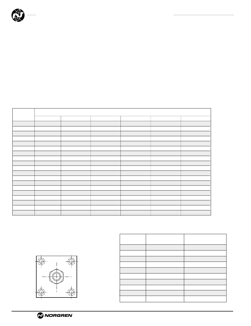
Tie Rod Tightening:
In order to reduce the possibility of cylinder binding or damage,
tighten to quarter unit increments of the final torque value in the
following order: #1, #2, #3, #4.
Then torque fully to the recommended foot pounds in the same order.
Determining Adequate Rod Diameter Chart
Note: In some cases it may be necessary to use a larger bore cylinder than is required
for force in order to obtain an adequate rod diameter.
1
3
4
2
Recommended Torques for Tightening Tie Rods
Extended
Maximum effective length “L”
Force
recommended for rod diameters
(lbs)
5/8"
1"
1-3/8"
1-3/4"
2"
2-1/2"
50
95
–
–
–
–
–
100
65
170
–
–
–
–
150
50
135
260
–
–
–
200
43
115
220
–
–
–
300
34
93
180
300
–
–
500
25
70
135
250
–
–
750
20
56
110
185
250
–
1000
17
48
94
160
220
–
1500
13
38
80
130
170
260
2000
11
33
64
110
140
225
3000
9
26
51
90
115
180
4000
7
22
44
75
100
155
5000
–
20
39
66
88
140
6000
–
18
35
60
79
125
8000
–
15
30
52
68
110
10000
–
12
26
46
60
95
12500
–
10
22
41
52
86
15000
–
–
19
37
48
79
20000
–
–
14
29
41
68
Cylinder
Standard
Stainless Steel
Bore
Steel Tie Rods
Tie Rods
1-1/2"
6.6 ft. lbs.
3.75 ft. lbs.
2"
11 ft. lbs.
7.5 ft. lbs.
2-1/2"
13 ft. lbs.
7.5 ft. lbs.
3-1/4"
20 ft. lbs.
13-14 ft. lbs.
4"
24 ft. lbs.
13-14 ft. lbs.
5"
40 ft. lbs.
33 ft. lbs.
6"
48 ft. lbs.
33 ft. lbs.
7" & 8"
100 ft. lbs.
65 ft. lbs.
10"
150 ft. lbs.
75 ft. lbs.
12"
175 ft. lbs.
87.5 ft. lbs.