Norgren NFPA Aluminum & Steel Cylinders User Manual
Page 88
ACT-1-88
Brookville, OH USA
Phone 937-833-4033
www.norgren.com
Series A & EA, NFPA Aluminum Air Cylinders (ø1-1/2 to 8")
Series J & EJ, NFPA Steel Air Cylinders (ø1-1/2 to 12")
Pneumatic & Pneulectric Valves Shown
Stroke Signal Valve
Stroke Signal Valves emit a positive pneumatic signal to indicate
the position of the piston at each end of the cylinder stroke.
It can be used to energize other air or electrical mechanisms
in a control circuit.
The design involves a three-way normally closed poppet valve that
uses the same pressure that drives the cylinder piston
to provide a pneumatic signal.
Stroke Signal Valves are positioned on either or both ends of the
cylinder according to your specifications. Each cylinder bore has
minimum stroke limitations (See page ACT-1-89.) The standard
Signal Valve begins to give a pneumatic signal when the cylinder
piston is within 1/8" of the end of the stroke. For signal distances
less than 1/8", consult factory.
Pneulectric Valve
Pneulectric valves incorporate a single-pole, double-throw electric
conversion switch with a Stroke Signal Valve. (Optional double-pole,
double-throw switches are available.)
The electric conversion switch screws directly into the outlet port
of the Stroke Signal Valve, enabling the Pneulectric Valve to convert
air pulses into electrical signals without the need of complicated
electro-pneumatic circuitry.
How to Order Stroke Signal Valves
Add suffix SV ( ) after cylinder model number.
Indicate in ( ) Stroke Signal Valve location: list head position first,
cap position last.
Valve position on head and/or cap should be indicated by position
number 1, 2, 3 or 4.
Example: J333A1-SV(02) – Bore x Stroke = Stroke Signal Valve
mounted on cap end only, position 2.
How to Order Pneulectric Valves
Add suffix EV after cylinder model number.
Example: J333A1-EV(42S)** – Bore x Stroke = Pneulectric Valve
mounted on head end, position 4 and cap end, position 2, with
single-pole – Double-throw.
** S = Single-pole – Double-throw switch
D = Double-pole – Double-throw switch
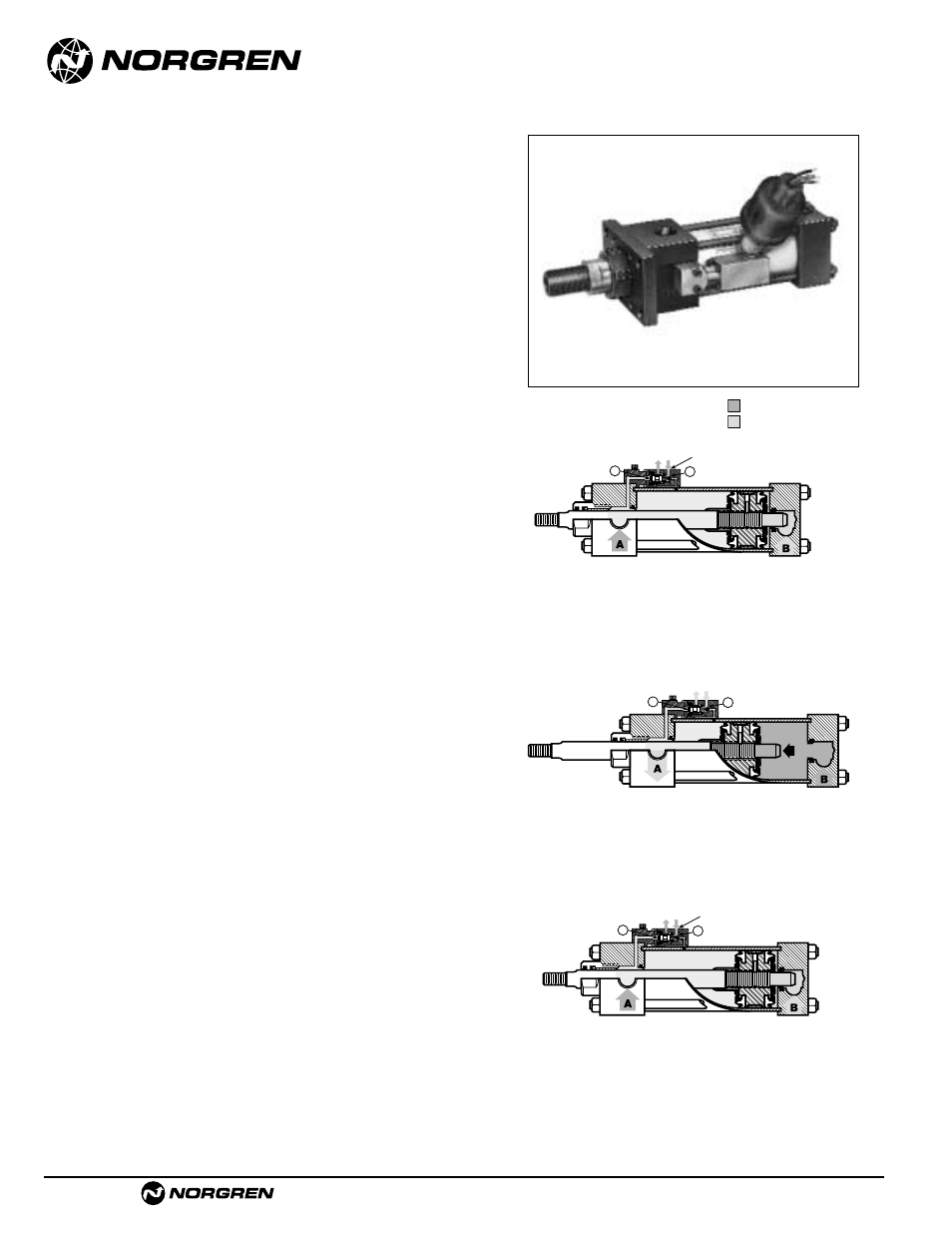
How the Valve Works
Start of the Stroke
At the start of the stroke, the stroke signal valve is closed
because areas (1) and (2) are equally pressurized (A), with
area (1) being several times greater than area (2). Outlet
port is vented to atmosphere.
Mid-Stroke
The same condition exists at mid-stroke with the
exception that a greater pressure (B) has been applied
to drive the piston.
End of the Stroke
†
At the end of the stroke the piston seal has passed the
inboard air hole (3), supplying full pressure against area
(2) When air has exhausted through (A) the valve stem
shifts and pressure is supplied to the outlet port of the
signal valve.
†
1/8" from bottoming.
1
2
OUTLET PORT
1
2
1
2
OUTLET PORT
SUPPLY PRESSURE
EXHAUST PRESSURE