Front panel i/o connectivity design guide – MSI 760GM-P33 User Manual
Page 18
18
Chassis intrusion Connector: JCi1
this connector connects to the chassis intrusion switch cable. if the chassis is
opened, the chassis intrusion mechanism will be activated. the system will record
this status and show a warning message on the screen. to clear the warning, you
must enter the BiOS utility and clear the record.
1.CIN
TRU
2.Gro
und
Clear CMOS Jumper: JBat1
there is a CMOS raM onboard that has a power supply from an external battery
to keep the data of system configuration. With the CMOS raM, the system can
automatically boot OS every time it is turned on. if you want to clear the system
configuration, set the jumper to clear data.
1
1
1
JBat1
Keep Data
Clear Data
iMPOrtant
You can clear CMOS by shorting 2-3 pin while the system is off. then return to
1-2 pin position. avoid clearing the CMOS while the system is on; it will damage
the mainboard.
Parallel Port header: JlPt1
this connector is used to connect an optional parallel port bracket. the parallel
port is a standard printer port that supports Enhanced Parallel Port (EPP) and
Extended Capabilities Parallel Port (ECP) mode.
10.G
roun
d
14.G
roun
d
8.LP
T_S
LIN#
12.G
roun
d
6.PIN
IT#
4.ER
R#
2.AF
D#
24.G
roun
d
22.G
roun
d
26.N
o Pin
20.G
roun
d
18.G
roun
d
16.G
roun
d
1.RS
TB#
3.PR
ND0
5.PR
ND1
7.PR
ND2
9.PR
ND3
11.P
RND
4
13.P
RND
5
15.P
RND
6
17.P
RND
7
19.A
CK#
21.B
USY
23.P
E
25.S
LCT
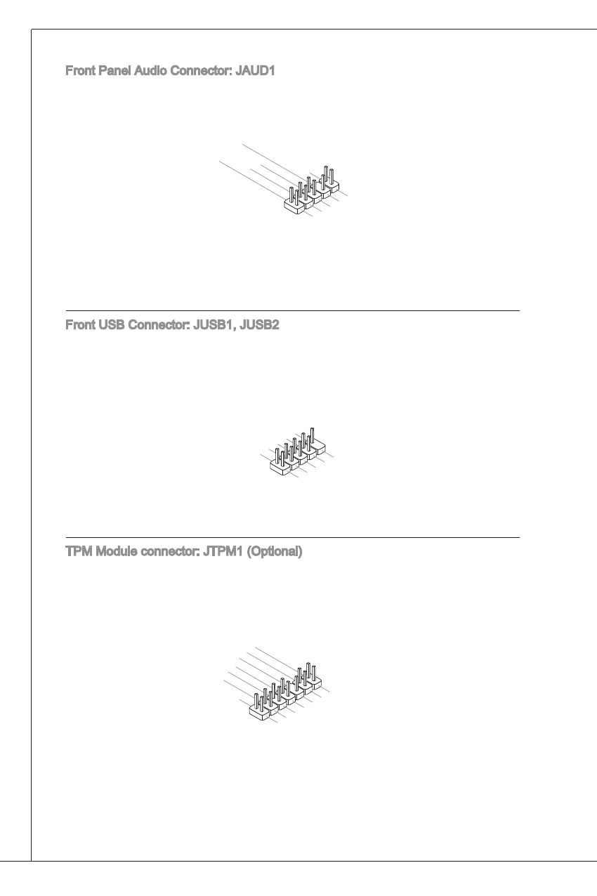
Front Panel audio Connector: JaUD1
this connector allows you to connect the front panel audio and is compliant with
intel
®
Front Panel i/O Connectivity Design guide.
1.M
IC L
3.M
IC R
10.H
ead P
hone
Dete
ction
5.He
ad P
hone
R
7.SE
NSE
_SE
ND
9.He
ad P
hone
L
8.No
Pin
6.M
IC D
etec
tion
4.PR
ESE
NCE
#
2.Gro
und
Front USB Connector: JUSB1, JUSB2
this connector, compliant with intel
®
i/O Connectivity Design guide, is ideal for
connecting high-speed USB interface peripherals such as USB hDD, digital cam-
eras, MP3 players, printers, modems and the like.
1.VC
C
3.US
B0-
10.U
SBO
C
5.US
B0+
7.Gro
und
9.No
Pin
8.Gro
und
6.US
B1+
4.US
B1-
2.VC
C
tPM Module connector: JtPM1 (Optional)
this connector connects to a tPM (trusted Platform Module) module. Please re-
fer to the tPM security platform manual for more details and usages.
10.N
o Pin
14.G
roun
d
8.5V
Pow
er
12.G
roun
d
6.Se
rial IR
Q
4.3.3
V Po
wer
2.3V
Stan
dby p
ower
1.LP
C Clo
ck
3.LP
C Re
set
5.LP
C ad
dres
s & d
ata p
in0
7.LP
C ad
dres
s & d
ata p
in1
9.LP
C ad
dres
s & d
ata p
in2
11.L
PC a
ddre
ss &
data
pin3
13.L
PC F
ram
e