Cs8130 – Cirrus Logic CS8130 User Manual
Page 9
The modulation frequency is determined by the
modulator divider registers. The transmit bit rate
is determined by the TV Remote transmit bit rate
divider. The UART to CS8130 baud rate must be
set to at least 20% faster than the transmit bit
rate.
Receive Path
A PIN diode is attached to the PINA and PINC
pins. Compensation for the DC ambient light is
applied to the photocurrent from the diode. The
change in photocurrent from ambient is ampli-
fied and compared to a threshold value. If the
photocurrent is greater than the set threshold, the
output is set to ’light’. If the photocurrent is less
than the set threshold, the output is set to ’no
light’. The threshold current is programmable.
This allows users to make the tradeoff between
noise immunity and the reliable transmission dis-
tance of the link. The PIN diode amplifier has a
bandpass filter characteristic, to limit the effects
of IR interference. The resulting logic signal is
further qualified, depending on the IR format se-
lected.
An autodetect feature is provided. If autodetect
mode is enabled, and transmit TV remote mode
is disabled, the FORM/BSY output pin indicates
the format of incoming data. If high, then the
incoming data is in IrDA/HPSIR format. If low,
the data is in ASK format which matches the
programmed modulation frequency.
Mode 1 (IrDA) Receive Choices
For Mode 1a, a logic circuit is set to only look
for pulse widths of 1.6
µ
s. For Mode 1b, a logic
circuit looks for pulses of 3/16 of the set baud
rate bit period. For Mode 1c, a logic circuit
looks for pulse widths of
≥
1.6
µ
s, but
≤
3/16 of
the set baud rate bit period.
Mode 2 (ASK) Receive Choices
For Mode 2, a logic circuit looks for sequences
of ’light’ and ’no light’ which matches the ex-
pected 500kHz carrier. The modulator divider
registers must be set to 6. The ASK receive tim-
ing sensitivity register should be set to 0,
yielding a valid incoming frequency range of
461 kHz to 614 kHz.
The RXD data transitions will lag behind the in-
frared activity by 3 modulation cycles. This
allows the modulation detect circuit time to ver-
ify the correct modulation frequency.
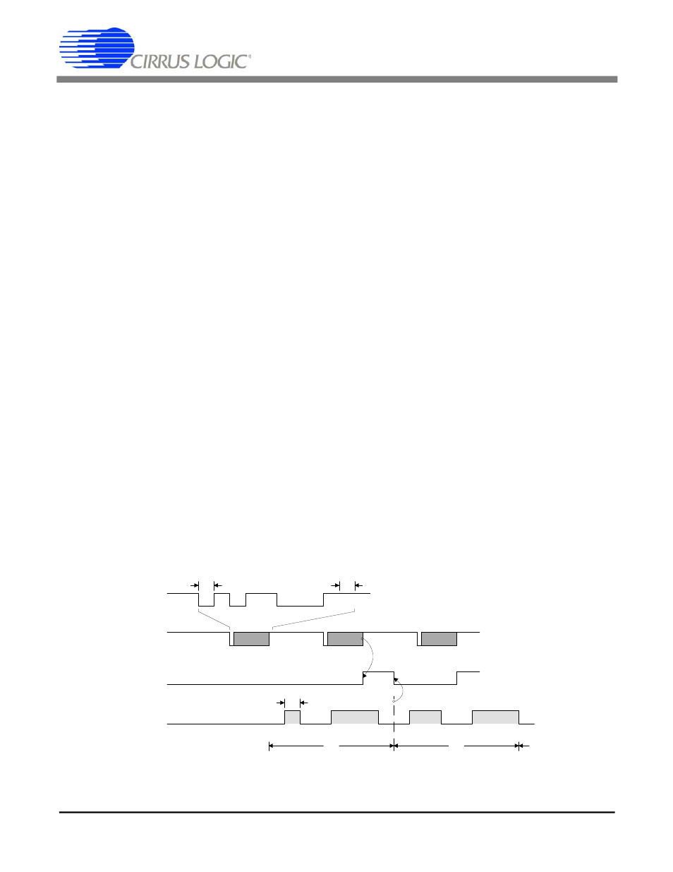
1
0
1
1
0
0
0
1
1
0
1
0
0
0
1
0
0
1
1
0
0
0
1
Start
Bit
Stop
Bit
A
B
C
1/2400
1
1
A
B
C
ON
OFF
* TXD Baud rate can be set
from 4800 to 115200 bps
LED
OUTPUT
FORM/BSY
TXD*
TXD*
Figure 5. Mode 3 (TV Remote) Transmit Data Format
CS8130
DS134PP2
9
CS8130
DS134F1
9