Cs8130, Figure 9. example pod schematic – Cirrus Logic CS8130 User Manual
Page 24
VA+
VD+
AGND
PINC
PINA
LED1C
LED2C
RESET
TGND1 TGND2 DGND
EXTCLK
XTALIN
XTALOUT
RXD
FORM/BSY
TXD
D/C
PWRDN
CLKFR
8
12
5
7
6
1
4
11
19
17
18
13
16
14
15
10
9
2
3
20
0.1
µ
F
+
10
µ
F
+3V
0.1
µ
F
+
10
µ
F
+
47
µ
F
+3V
10
Ω
5.5
Ω (2)
5.5
Ω (2)
+3V
3.6864 MHz
15
EN
SHDN
+3V
CIA-
CIA+
T1IN
T2IN
R1OUT
R2OUT
CS8130
MAX562
VCC
CIB-
CIB+
T1OUT
T2OUT
R1IN
R2IN
V-
V+
GND
27
28
26
22
23
17
18
3
4
1
5
2
11
12
6
7
0.33
µ
F
+3V
0.33
µ
F
0.33
µ
F
C2+
C2-
24
25
0.33
µ
F
0.68
µ
F
0.33
µ
F
5
4
3
8
2
RXD
CTS
TXD
DTR
DB9
Serial
Connector
(COM PORT)
BPV23NF
TSHA5502
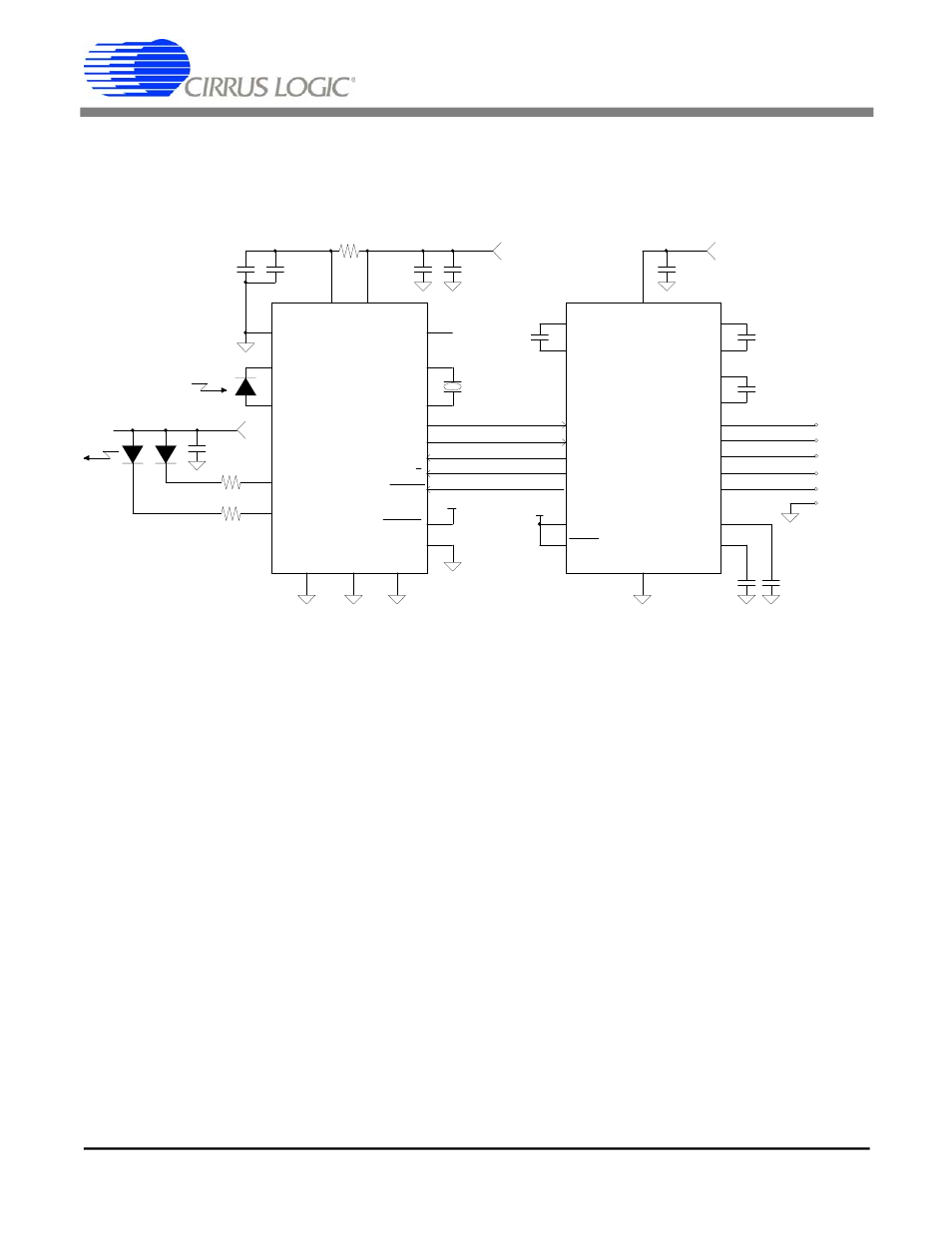
RS232 COM PORT to Infra Red Interface
Pod Schematic
Steven Harris
Crystal Semiconductor
5/26/94
14
Notes:
(1) This circuit has not yet been built and debugged.
(2) Choice of LED, power consumption and physical positioning will affect R value.
(3) The creation of +3V or +5V supply is not included here.
R3IN
21
7
RTS
R3OUT
8
Figure 9. Example Pod Schematic
CS8130
24
DS134PP2
CS8130
24
DS134F1
- CobraNet (147 pages)
- CS4961xx (54 pages)
- CS150x (8 pages)
- CS1501 (16 pages)
- CS1601 (2 pages)
- CS1601 (16 pages)
- CS1610 (16 pages)
- CRD1610-8W (24 pages)
- CRD1611-8W (25 pages)
- CDB1610-8W (21 pages)
- CS1610A (18 pages)
- CDB1611-8W (21 pages)
- CDB1610A-8W (21 pages)
- CDB1611A-8W (21 pages)
- CRD1610A-8W (24 pages)
- CRD1611A-8W (25 pages)
- CS1615 (16 pages)
- AN403 (15 pages)
- AN401 (14 pages)
- AN400 (15 pages)
- AN375 (27 pages)
- AN376 (9 pages)
- CRD1615-8W (22 pages)
- CRD1616-8W (23 pages)
- AN402 (14 pages)
- AN404 (15 pages)
- CRD1615A-8W (21 pages)
- CS1615A (16 pages)
- CS1630 (56 pages)
- AN374 (35 pages)
- AN368 (80 pages)
- CRD1630-10W (24 pages)
- CRD1631-10W (25 pages)
- CS1680 (16 pages)
- AN405 (13 pages)
- AN379 (31 pages)
- CRD1680-7W (31 pages)
- AN335 (10 pages)
- AN334 (6 pages)
- AN312 (14 pages)
- AN Integrating CobraNet into Audio Products (16 pages)
- CobraNet Audio Routing Primer (9 pages)
- Bundle Assignments in CobraNet Systems (3 pages)
- CS2300-01 (3 pages)
- CS2000-CP (38 pages)