Cs8130 – Cirrus Logic CS8130 User Manual
Page 25
Power Supplies
VD+ - Digital Positive Supply.
Digital positive supply voltage. Nominally +3V
VA+ - Analog Positive Supply.
Analog positive supply voltage. Nominally +3V.
DGND - Digital Ground.
Digital ground, 0V, connection.
AGND - Analog Ground.
Analog ground, 0V, connection.
TGND1, TGND2 - Transmitter Grounds.
LED Transmitter grounds, 0V, connections.
Analog Pins
LED1C, LED2C - Transmit LED Cathode.
These pins are connected to the transmit LED cathode via resistors. Appropriate resistor choice
allows user setting of LED current options. The anode of the LED is connected to the positive
supply.
PINC - Receiver PIN Diode Cathode
Receiver PIN diode cathode.
PINA - Receiver PIN Diode Anode.
Receiver PIN diode anode.
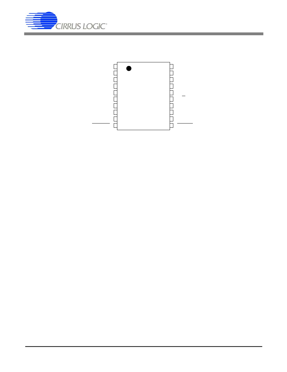
LED1 CATHODE
LED1C
DGND
DIGITAL GROUND
TRANSMIT GROUND 1
TGND1
EXTCLK
EXTERNAL CLOCK
TRANSMIT GROUND 2
TGND2
XTALOUT
CRYSTAL OUTPUT
LED2 CATHODE
LED2C
XTALIN
CRYSTAL INPUT
ANALOG GROUND
AGND
FORM/BSY
FORMAT/BUSY
PIN DIODE ANODE
PINA
D/C
DATA/CONTROL
PIN DIODE CATHODE
PINC
TXD
TRANSMIT DATA
ANALOG SUPPLY
VA+
RXD
RECEIVE DATA
CLOCK FREQUENCY
CLKFR
VD+
DIGITAL SUPPLY
POWER DOWN
PWRDN
RESET
RESET
1
2
3
4
5
6
7
8
9
10
20
19
18
17
16
15
14
13
12
11
CS8130
DS134PP2
25
CS8130
DS134F1
25