Pin description, Cs5466 – Cirrus Logic CS5466 User Manual
Page 4
CS5466
4
DS659F2
2.
PIN DESCRIPTION
Clock Generator
Crystal Out
Crystal In
1, 24
XOUT, XIN - A single stage amplifier inside the chip is connected to these pins and can be used
with a crystal to provide the system clock for the device. Alternatively, an external clock can be
supplied to the XIN pin to provide the system clock for the device.
CPU Clock Output
2
CPUCLK - Output of on-chip oscillator which can drive one standard CMOS load.
Control Pins
Gain Select
5, 7
IGAIN1, IGAIN0 - Used to select the current channel input gain range.
Frequency Select
17, 20, 23
FREQ2,FREQ1,FREQ0 - Used to select max pulse output frequency for E1, E2, and FOUT.
High Pass Filter Enable
8
HPF - High disables the HPF. Low activates HPF on Voltage channel. Connecting HPF pin to
FOUT pin activates HPF on Current channel.
Reset
19
RESET - Low activates Reset.
Energy Pulse Outputs
Energy Output
22, 21
E1, E2 - Active low alternating pulses with an output frequency that is proportional to the active
(real) power.
High Freq Output
18
FOUT - Outputs energy pulses at a frequency higher than E1 and E2 outputs. Used for calibra-
tion purposes.
Neg Energy Indicator
6
NEG - High indicates negative energy.
Analog Inputs/Outputs
Differential Voltage Inputs
9, 10
VIN+, VIN- - Differential analog input pins for voltage channel.
Voltage Reference
Output
11
VREFOUT - The on-chip voltage reference output pin. The voltage reference has a nominal
magnitude of 2.5 V and is referenced to the AGND pin on the converter.
Voltage Reference Input
12
VREFIN - Voltage input to this pin establishes the voltage reference for the on-chip modulators.
Differential Current Inputs
16, 15
IIN+, IIN- - Differential analog input pins for current channel.
Power Supply Connections
Positive Digital Supply
3
VD+ - The positive digital supply.
Digital Ground
4
DGND - Digital Ground.
Analog Ground
13
AGND - Analog Ground.
Positive Analog Supply
14
VA+ - The positive analog supply.
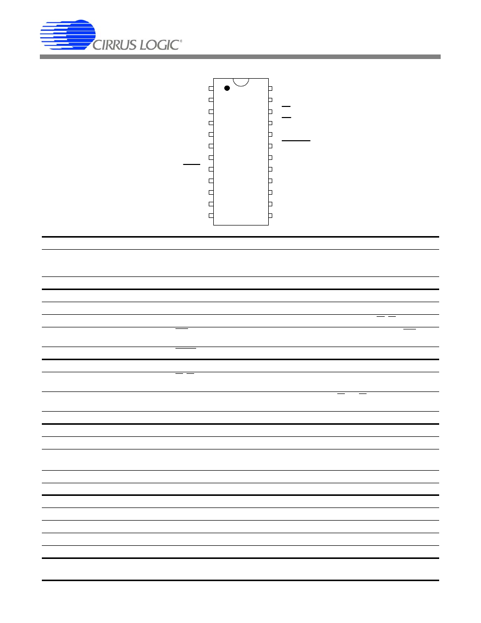
VREFIN
12
Voltage Reference Input
VREFOUT
11
Voltage Reference Output
VIN-
10
Differential Voltage Input
VIN+
9
Differential Voltage Input
HPF
8
High-pass Filter Enable
IGAIN1
7
Gain Select 1
NEG
6
Negative Energy Indicator
IGAIN0
5
Gain Select 0
DGND
4
Digital Ground
VD+
3
Positive Power Supply
CPUCLK
2
CPU Clock Output
XOUT
1
Crystal Out
AGND
13
Analog Ground
VA+
14
Positive Analog Supply
IIN-
15
Differential Current Input
IIN+
16
Differential Current Input
FREQ2
17
Frequency Select 2
FOUT
18
High-frequency Output
RESET
19
Reset
FREQ1
20
Frequency Select 1
E2
21
Energy Output 2
E1
22
Energy Output 1
FREQ0
23
Frequency Select 0
XIN
24
Crystal In