7 basic application circuit, Figure 4. typical connection diagram, Cs5466 – Cirrus Logic CS5466 User Manual
Page 14
CS5466
14
DS659F2
5.7
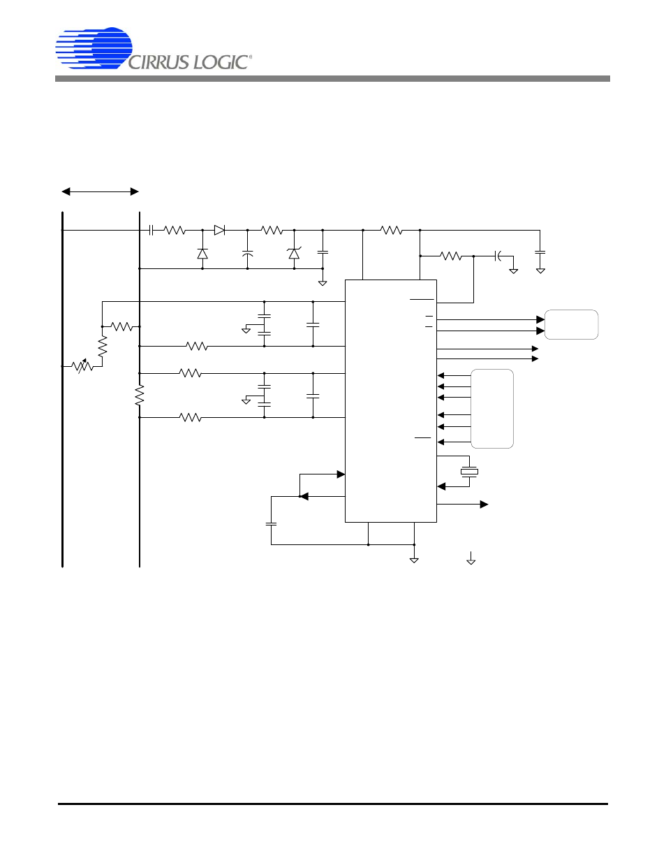
Basic Application Circuit
Figure 4 shows the CS5466 configured to measure
power in a single-phase, 2-wire system while operating
in a single-supply configuration. In this diagram, a shunt
resistor is used to sense the line current and a voltage
divider is used to sense the line voltage. In this type of
shunt resistor configuration, the common-mode level of
the CS5466 must be referenced to the line side of the
power line. This means that the common-mode poten-
tial of the CS5466 will track the high voltage levels, as
well as low voltage levels, with respect to earth ground
potential.
EDIR / P4
VD+
FOUT
XOUT
XIN
CPUCLK
DGND
VA-
VREFOUT
VREFIN
IIN+
IIN-
VIN-
VIN+
AGND
3
15
14
9
10
16
12
11
13
4
2
24
1
18
22
21
120 VAC
10
500
500
470 nF
470 F
0.1 F
0.1
F
R
SHUNT
0.1
F
R
1
N
L
AGND
VA+
E2
E1
R
I+
R
I-
R
V-
C
Idiff
C
Vdiff
C
V-
C
V+
C
I+
C
I-
FREQ2
17
FREQ1
20
FREQ0
23
IGAIN1
7
IGAIN0
5
NEG
6
IHPF
8
Stepper
Motor
5466
Config.
Settings
4.096 MHz
10 k
1 F
RESET
Calibratio
n
Resistor
Note:
Indicates common (floating) return.
R
2
19
Figure 4. Typical Connection Diagram