Functional description, 1 analog inputs, 1 voltage channel – Cirrus Logic CS5466 User Manual
Page 11: 2 current channel, 2 high-pass filter, 3 energy pulse outputs, 1 pulse output format, 2 selecting frequency of e1 and e2, 1 voltage channel 5.1.2 current channel, 2 high-pass filter 5.3 energy pulse outputs
CS5466
DS659F2
11
5.
FUNCTIONAL DESCRIPTION
5.1
Analog Inputs
The CS5466 is equipped with two fully differential input
channels. The inputs VIN
and IIN are designated as
the voltage and current channel inputs, respectively.
The full-scale differential input voltage for the current
and voltage channel is
250 mV
P
.
5.1.1
Voltage Channel
The output of the line-voltage resistive divider or trans-
former is connected to the VIN+ and VIN- input pins of
the CS5466. The voltage channel is equipped with a
10x, fixed-gain amplifier. The full-scale signal level that
can be applied to the voltage channel is
250 mV. If the
input signal is a sine wave, the maximum RMS voltage
is:
which is approximately 70.7% of maximum peak volt-
age.
5.1.2
Current Channel
The output of the current-sense resistor or transformer
is connected to the IIN+ and IIN- input pins of the
CS5466. To accommodate different current-sensing de-
vices, the current channel incorporates programmable
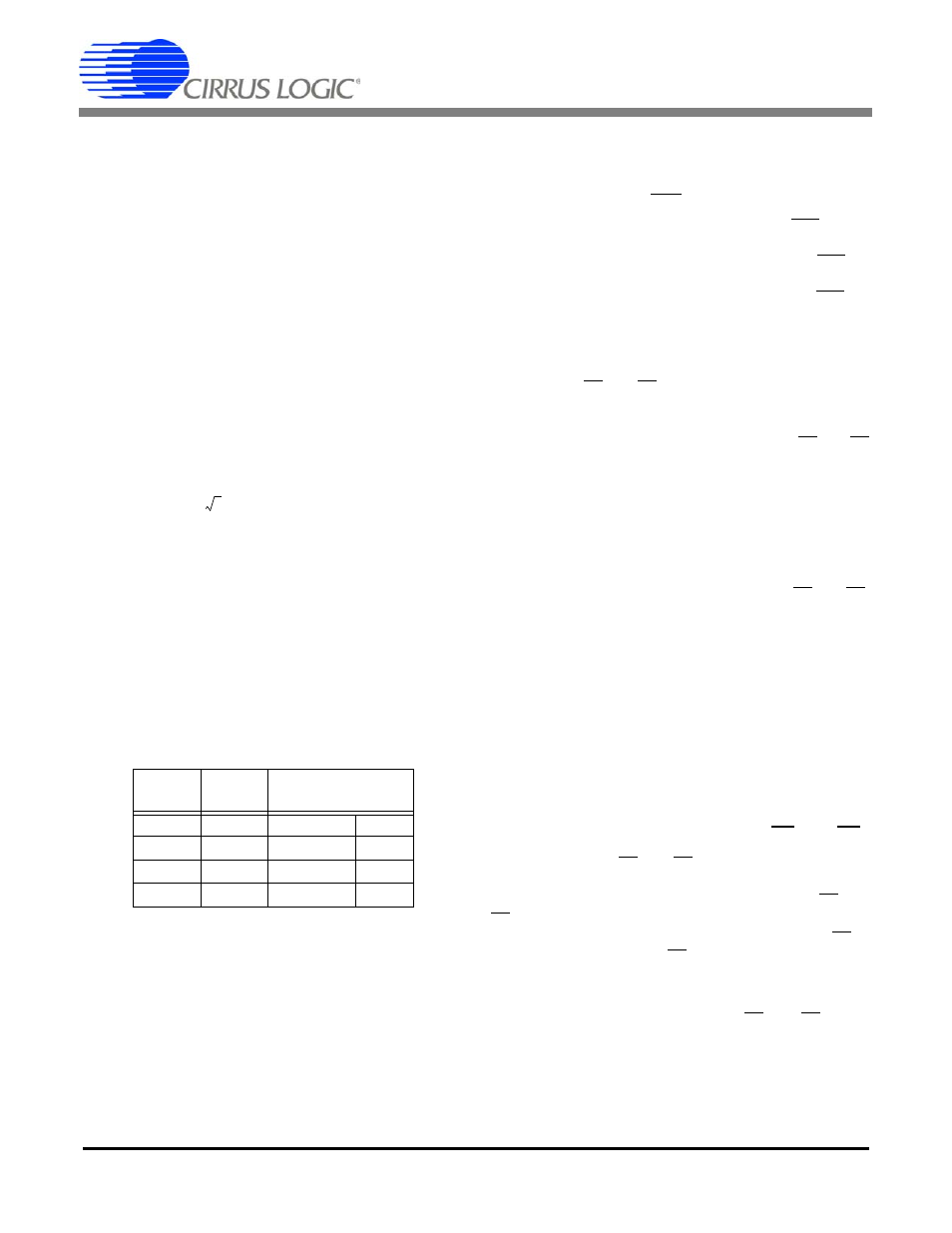
gains which can be set to one of four input ranges. Input
pins IGAIN1 and IGAIN0 (See Table 1) define the four
gain selections and corresponding maximum input sig-
nal level.
For example, if IGAIN1=IGAIN0=0, the current chan-
nel’s gain is set to 10x. If the input signals are pure sinu-
soids with zero phase shift, the maximum peak
differential signal on the current or voltage channel is
250 mV
P
. The input signal levels are approximately
70.7% of maximum peak voltage producing a full-scale
energy pulse registration equal to 50% of absolute max-
imum energy pulse registration. This will be discussed
further in Section 5.3
5.2
High-pass Filter
By removing the offset from either channel, no error
component will be generated at DC when computing the
active power. Input pin HPF defines the three options:
– High-pass Filter (HPF) is disabled when pin HPF is
connected high.
– HPF is enabled in the voltage channel when pin HPF is
connected low.
– HPF is enabled in the current channel when pin HPF is
connected to pin FOUT.
5.3
Energy Pulse Outputs
The CS5466 provides three output pins for energy reg-
istration. The E1 and E2 pins provide a simple interface
from which energy can be registered. These pins are
designed to directly connect to a stepper motor or elec-
tromechanical counter. The pulse rate on the E1 and E2
pins are in the range of 0 to 4 Hz and all frequency set-
tings are optimized to be used with standard meter con-
stants. The FOUT pin is designated for system
calibration and the pulse rate can be selected to reach
a frequency of 8000 Hz.
5.3.1
Pulse Output Format.
The CS5466 produces alternating pulses on E1 and E2.
This pulse format is designed to drive a stepper motor.
Each pin produces active-low pulses with a minimum
pulse width of 250 ms when MCLK = 4.096 MHz. Refer
to
on page 8 for timing pa-
rameters.
The FOUT pin issues active-high pulses. The pulse
width is equal to 90 ms (typical), unless the period falls
below 180 ms. At this time the pulses will be equal to
half the period. In mode 3 (FREQ[2:0] = 3), the pulse
width of all FOUT pulses is typically 20
s regardless of
the pulse rate (MCLK = 4.096 MHz).
5.3.2
Selecting Frequency of E1 and E2
The pulse rate on E1 and E2 can be set to one of four
frequency ranges. Input pins FREQ1 and FREQ0 (See
Table 2) determine the maximum frequency on E1 and
E2 for pure sinusoidal inputs with zero phase shift. As
shown in
, the frequency of E2 is
equal to the frequency of E1 with active-low alternating
pulses.
As discussed in Section 5.1.2
11, the maximum frequency on the E1 and E2 output
pins is equal to the selected frequency in Table 2 if the
maximum peak differential signal applied to both chan-
nels is a sine wave with zero phase shift.
IGAIN1
IGAIN0
Maximum Input
Range
0
0
±250mV
10x
0
1
±50mV
50x
1
0
±25mV
100x
1
1
±16.67mV
150x
Table 1. Current Channel PGA Setting
250mV
P
2
-----------------
176.78mV
RMS